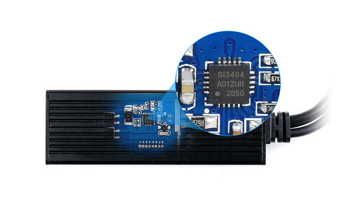
In the hope that it will be useful to others, I thought I'd share my testing of the C8 powered via PoE.
There have been many references to issues when powering C7/C8 units using Unifi switches, but it should be understood that these issues are not specific to Unifi. My main switches are Cisco CBS 350s (192W), and while I had no issues powering C7s with inexpensive lightweight PoE splitters, the C8 has been a completely different story. FWIW, I've also tested with a dedicated Trendnet PoE switch (120W) with similar results to my Ciscos.
To be clear: I do not doubt the reports that that there are some switches, in some configurations, that do not have an issue. Nor do I doubt the reports that many Unifi switches have problems. That said, I believe that the majority of the issue lies with the splitters rather than the switches. I also believe that there are people with C8s on splitters that have issues, but do not notice because the hub still performs adequately. Lastly, I do not have any Zigbee devices, so I cannot speak to the reports that Zigbee is not affected. I have only tested with Z-Wave.
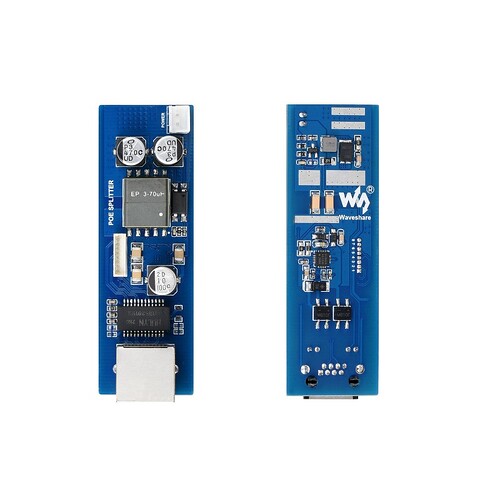
I tested 10 different models of USB-C PoE splitters with the C-8. With a few, I also tested multiple copies of the same model to confirm findings. I have made good use of Free Delivery & Free Returns from Amazon.
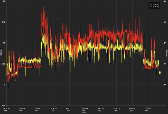
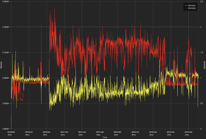
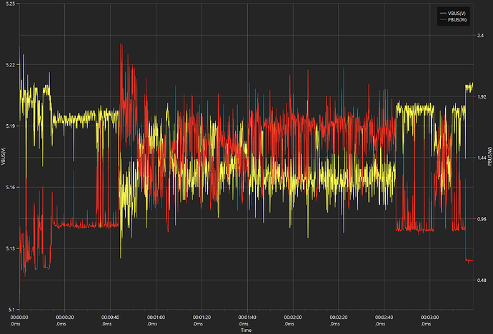
For those that want to skip the gory detail, the take home point is this: My opinion is that Z-Wave on the C8 appears to be very sensitive to voltage fluctuations.
If you want the gory detail, read on...
How I tested
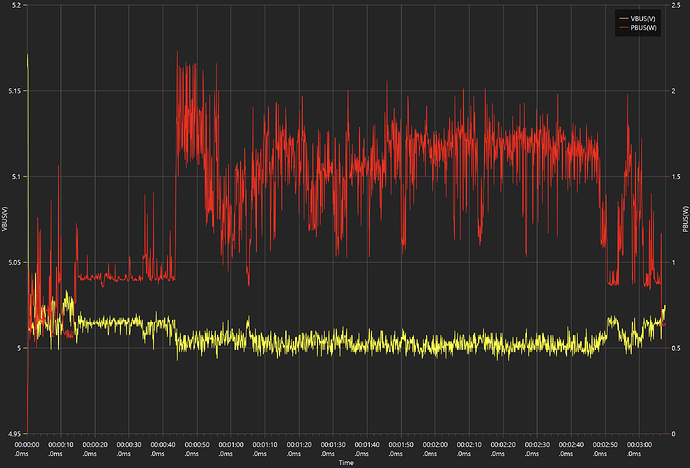
When I started out I had a simple USB meter available, so I tried it with some of the splitters. I saw voltage fluctuations during heavy transmit, but wasn't able to tell much more with a simple meter. After a bit of soul searching, I found a scope style meter that I was willing to take a chance on. This clarified things a lot.
The test I run looks like this:
-
Plug in the hub's USB connection. This starts the data logging.
-
Wait for the green light on the hub.
-
Wait a brief period of time (down off the ladder and walk back to my office).
-
Perform a refresh on the problematic device while monitoring the sniffer.
-
If the first refresh works well, do it again for good measure.
-
Initiate a shutdown of the hub.
-
Stop the data logging when the red light appears.
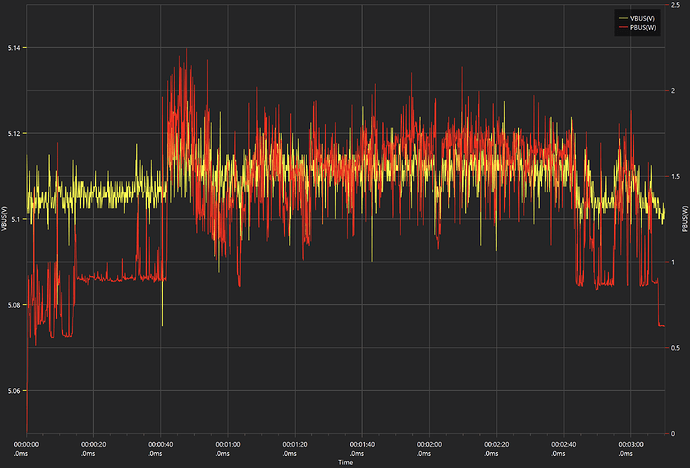
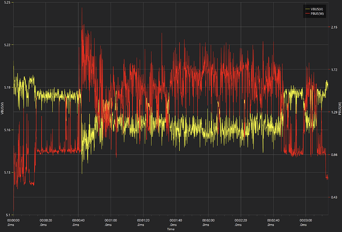
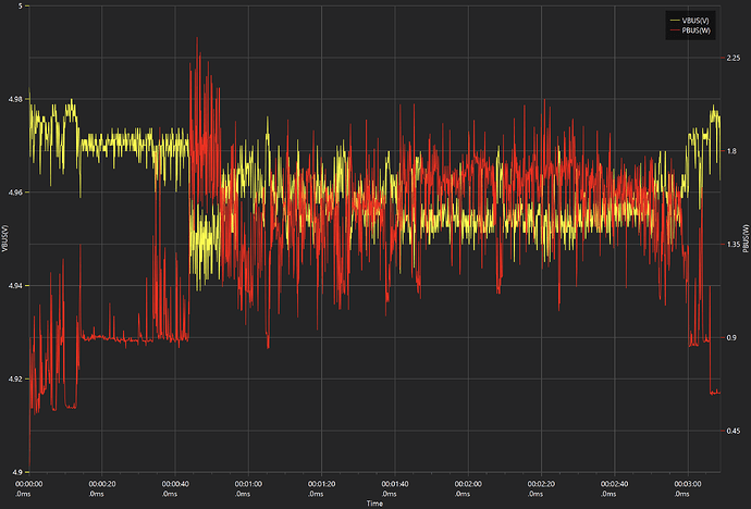
For each graph shown, yellow is the voltage (V) and red is the power (W). The refresh on the problematic device is generally the power spike shortly after 3:00 in the graphs. Note that the software does not allow me to fix the Y axis, so there is some slight variation from graph to graph.
The brick:
For reference, here is a graph of what the test looks like on the included brick:
As you can see, the voltage is relatively stable, and holds or pushes up as the power requirement increases.
I am not an electrical engineer. That said, my opinion is that the splitters that work are ones that have isolated switch-mode power supplies (SMPS) with good voltage regulators. This makes them heavier, and generally more expensive, but they work reliably. I'm sure that there are other splitters of this ilk that can be found, but I've come to the end of my project for now.
YMMV
Now on to the splitters...
