circuit to sense the Hub is powered down (just the red led) and remove power from the hub until mains power is back. This would allow the hub to be self starting.
Zigbee Module
to enable onboard power loss monitoring and graceful shutdown
enable battery state reporting
Feedback on these goals is very welcome, we fully intend to try and keep costs down as much as possible, so expensive suggestions may not get added to the list.
I've seen some projects where power failure triggers a safe shutdown routine on the hub.
would the power failure monitor have enough juice to run a tiny relay output to drive external contacts? That way you could hook up an external Zigbee/Zwave contact, without having to build it into the device.
Quite true, currently you need to guess how long the batteries will last, there’s also the shutdown time for the hub which can be around a minute or so.
We’ll certainly see what is possible without making this drastically more expensive than the OG version.
Interested also. Plus, I would be even more interested if you plan on an expandable/modular design.
Ability to communicate with the Hubitat itself (over the network, WiFi would be fine in my book). This could alleviate the need to watch the status LED. Plus the Hubitat could monitor it's own power supply status and determine when to shut down (and thus if it needs to shut down OTHER stuff first).
Ability to have added battery packs or a readily changeable pack if someone wants to give it more battery life.
Two RGB LEDs. 1 for "system status" (is it on/charging/draining/faulted). 2nd is for "battery status" (green = good, shades of yellow-orange as it drains, red is basically empty). Is these are controllable/configurable (see 1 above) all the better.
I have more ideas but I think the 1st of these is problematic enough but also the most important in my book.
EDIT:
For the casing, feel free to look at my thingiverse Hubitat wall mount or such. The OpenSCAD file is posted there so it has dimensions and other information that might be useful.
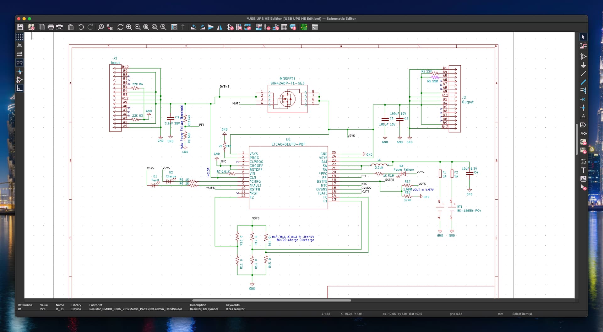
Just a word about the UPS controller for this project.
The core "brains" of the UPS is an full ups system IC PN: LTC4040 from Linear Technology/Analog devices.
This device is the "Cadillac"** of UPS controllers.
What I appreciate most is the ability to limit battery charge voltage. By reducing the charge voltage a little power is lost but is much better for the battery life. All the other battery charge IC's charge Li-on to the battery max of 4.2 volts. Then they hold it there for basically forever (as long as input power is present). This is a worst case operation for a Li-ion battery.
Other leading particulars:
Step-Up Backup Supply and Step-Down Battery Charger
6.5A Switches for 2.5A Backup from 3.2V Battery
Input Current Limit Prioritizes Load Over Charge Current
Input Disconnect Switch Isolates Input During Backup
Automatic Seamless Switch-Over to Backup Mode
Input Power Loss Indicator
System Power Loss Indicator
Selectable Battery: Li-Io(3.95V/4.0V/4.05V/4.1V) or LiFePO4 (3.45V/3.5V/3.55V/3.6V)