After Petnet went belly up and left everyone stranded, I kept thinking to myself I need to integrate this and get it smart again. Using the magic of nodemcu and HubDuino I have now made this a reality.
If anyone else is in this same boat, or want to pick up a cheap one from eBay, feel free to follow my guide below.
The button on the device is optional, and my instructions will include it. If you don't care about using the button on the device, just skip those steps.
Perform this at your own risk as YMMV. I'm not responsible if you break anything or shock yourself on low voltage.
.================.
ITEMS YOU'LL NEED
.================.
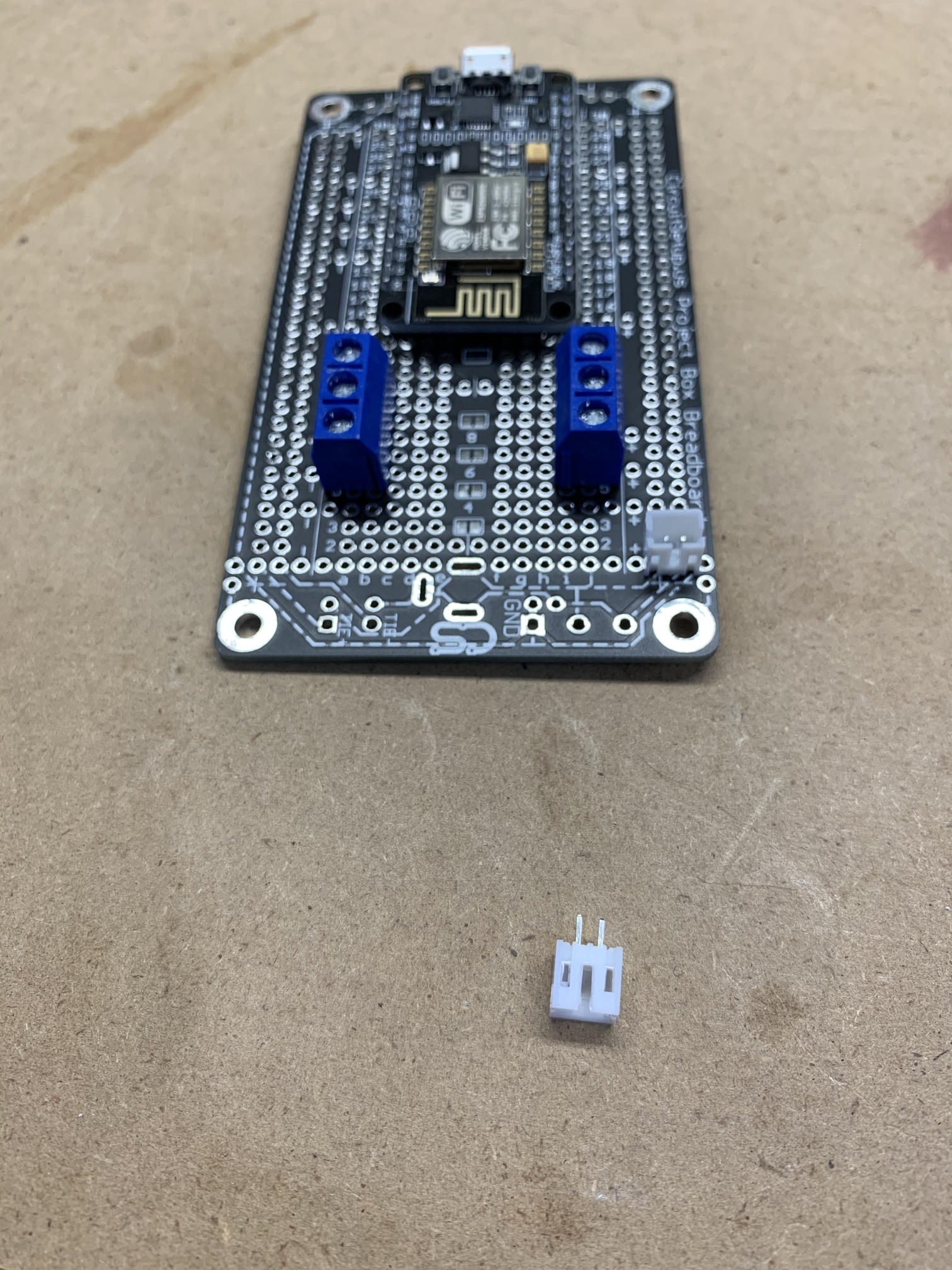
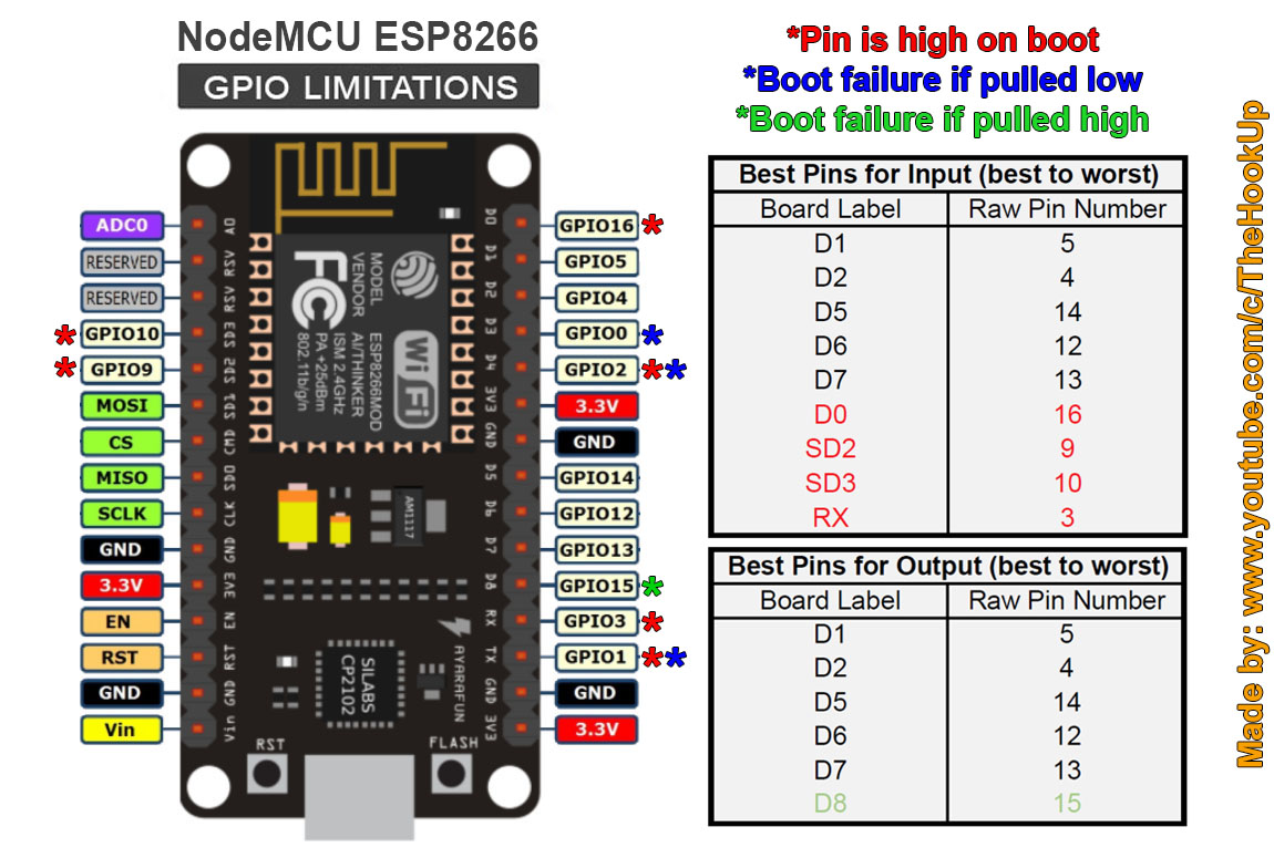
- NodeMCU
- 3.3V Relay
- Jumper wires
- 10K ohm resistor
.================.
THE CODE
.================.
Load the following code into your NodeMCU. Be sure to update the WiFi details and IP Address info for your local network
Summary
//******************************************************************************************
// File: ST_Anything_Multiples_ESP8266WiFi.ino
// Authors: Dan G Ogorchock & Daniel J Ogorchock (Father and Son)
//
// Summary: This Arduino Sketch, along with the ST_Anything library and the revised SmartThings
// library, demonstrates the ability of one NodeMCU ESP8266 to
// implement a multi input/output custom device for integration into SmartThings.
// The ST_Anything library takes care of all of the work to schedule device updates
// as well as all communications with the NodeMCU ESP8266's WiFi.
//
// ST_Anything_Multiples implements the following ST Capabilities as a demo of what is possible with a single NodeMCU ESP8266
// - 1 x Alarm device (using a simple digital output)
// - 1 x Contact Sensor devices (used to monitor magnetic door sensors)
// - 1 x Switch devices (used to turn on a digital output (e.g. LED, relay, etc...)
// - 1 x Motion devices (used to detect motion)
// - 1 x Smoke Detector devices (using simple digital input)
// - 1 x Temperature Measurement devices (Temperature from Dallas Semi 1-Wire DS18B20 device)
// - 1 x Relay Switch devices (used to turn on a digital output for a set number of cycles And On/Off times (e.g.relay, etc...))
// - 2 x Button devices (sends "pushed" if held for less than 1 second, else sends "held"
// - 1 x Water Sensor devices (using the 1 analog input pin to measure voltage from a water detector board)
//
// Change History:
//
// Date Who What
// ---- --- ----
// 2015-01-03 Dan & Daniel Original Creation
// 2017-02-12 Dan Ogorchock Revised to use the new SMartThings v2.0 library
// 2017-04-17 Dan Ogorchock New example showing use of Multiple device of same ST Capability
// used with new Parent/Child Device Handlers (i.e. Composite DH)
// 2017-05-25 Dan Ogorchock Revised example sketch, taking into account limitations of NodeMCU GPIO pins
// 2018-02-09 Dan Ogorchock Added support for Hubitat Elevation Hub
//
//******************************************************************************************
//******************************************************************************************
// SmartThings Library for ESP8266WiFi
//******************************************************************************************
#include <SmartThingsESP8266WiFi.h>
//******************************************************************************************
// ST_Anything Library
//******************************************************************************************
#include <Constants.h> //Constants.h is designed to be modified by the end user to adjust behavior of the ST_Anything library
#include <Device.h> //Generic Device Class, inherited by Sensor and Executor classes
#include <Executor.h> //Generic Executor Class, typically receives data from ST Cloud (e.g. Switch)
#include <Everything.h> //Master Brain of ST_Anything library that ties everything together and performs ST Shield communications
#include <EX_Switch.h> //Implements an Executor (EX) via a digital output to a relay
#include <IS_Button.h> //Implements an Interrupt Sensor (IS) to monitor the status of a digital input pin for button presses
//*************************************************************************************************
//NodeMCU v1.0 ESP8266-12e Pin Definitions (makes it much easier as these match the board markings)
//*************************************************************************************************
//#define LED_BUILTIN 16
//#define BUILTIN_LED 16
//
//#define D0 16 //no internal pullup resistor
//#define D1 5
//#define D2 4
//#define D3 0 //must not be pulled low during power on/reset, toggles value during boot
//#define D4 2 //must not be pulled low during power on/reset, toggles value during boot
//#define D5 14
//#define D6 12
//#define D7 13
//#define D8 15 //must not be pulled high during power on/reset
//******************************************************************************************
//Define which Arduino Pins will be used for each device
//******************************************************************************************
#define PIN_SWITCH_1 D0 //SmartThings Capability "Switch"
#define PIN_BUTTON_1 D2 //SmartThings Capabilty Button / Holdable Button (Normally Open!)
//******************************************************************************************
//ESP8266 WiFi Information
//******************************************************************************************
String str_ssid = "YOUR_SSID"; // <---You must edit this line!
String str_password = "YOUR_PASSWORD"; // <---You must edit this line!
IPAddress ip(192, 168, X, X); //Device IP Address // <---You must edit this line!
IPAddress gateway(192, 168, X, X); //Router gateway // <---You must edit this line!
IPAddress subnet(255, 255, 255, 0); //LAN subnet mask // <---You must edit this line!
IPAddress dnsserver(192, 168, X, X); //DNS server // <---You must edit this line!
const unsigned int serverPort = 8090; // port to run the http server on
// Smarthings Hub Information
//IPAddress hubIp(192, 168, 1, 149); // smartthings hub ip // <---You must edit this line!
//const unsigned int hubPort = 39500; // smartthings hub port
// Hubitat Hub Information
IPAddress hubIp(192, 168, X, X); // hubitat hub ip // <---You must edit this line!
const unsigned int hubPort = 39501; // hubitat hub port
//******************************************************************************************
//st::Everything::callOnMsgSend() optional callback routine. This is a sniffer to monitor
// data being sent to ST. This allows a user to act on data changes locally within the
// Arduino sktech.
//******************************************************************************************
void callback(const String &msg)
{
// Serial.print(F("ST_Anything Callback: Sniffed data = "));
// Serial.println(msg);
//TODO: Add local logic here to take action when a device's value/state is changed
//Masquerade as the ThingShield to send data to the Arduino, as if from the ST Cloud (uncomment and edit following line)
//st::receiveSmartString("Put your command here!"); //use same strings that the Device Handler would send
}
//******************************************************************************************
//Arduino Setup() routine
//******************************************************************************************
void setup()
{
//******************************************************************************************
//Declare each Device that is attached to the Arduino
// Notes: - For each device, there is typically a corresponding "tile" defined in your
// SmartThings Device Hanlder Groovy code, except when using new COMPOSITE Device Handler
// - For details on each device's constructor arguments below, please refer to the
// corresponding header (.h) and program (.cpp) files.
// - The name assigned to each device (1st argument below) must match the Groovy
// Device Handler names. (Note: "temphumid" below is the exception to this rule
// as the DHT sensors produce both "temperature" and "humidity". Data from that
// particular sensor is sent to the ST Hub in two separate updates, one for
// "temperature" and one for "humidity")
// - The new Composite Device Handler is comprised of a Parent DH and various Child
// DH's. The names used below MUST not be changed for the Automatic Creation of
// child devices to work properly. Simply increment the number by +1 for each duplicate
// device (e.g. contact1, contact2, contact3, etc...) You can rename the Child Devices
// to match your specific use case in the ST Phone Application.
//******************************************************************************************
//Interrupt Sensors
static st::IS_Button sensor1(F("button1"), PIN_BUTTON_1, 1000, HIGH, true, 500);
//Executors
static st::EX_Switch executor1(F("switch1"), PIN_SWITCH_1, LOW, false); //Inverted logic for "Active Low" Relay Board
//*****************************************************************************
// Configure debug print output from each main class
// -Note: Set these to "false" if using Hardware Serial on pins 0 & 1
// to prevent communication conflicts with the ST Shield communications
//*****************************************************************************
st::Everything::debug=true;
st::Executor::debug=true;
st::Device::debug=true;
st::InterruptSensor::debug=true;
//*****************************************************************************
//Initialize the "Everything" Class
//*****************************************************************************
//Initialize the optional local callback routine (safe to comment out if not desired)
st::Everything::callOnMsgSend = callback;
//Create the SmartThings ESP8266WiFi Communications Object
//STATIC IP Assignment - Recommended
st::Everything::SmartThing = new st::SmartThingsESP8266WiFi(str_ssid, str_password, ip, gateway, subnet, dnsserver, serverPort, hubIp, hubPort, st::receiveSmartString);
//DHCP IP Assigment - Must set your router's DHCP server to provice a static IP address for this device's MAC address
//st::Everything::SmartThing = new st::SmartThingsESP8266WiFi(str_ssid, str_password, serverPort, hubIp, hubPort, st::receiveSmartString);
//Run the Everything class' init() routine which establishes WiFi communications with SmartThings Hub
st::Everything::init();
//*****************************************************************************
//Add each executor to the "Everything" Class
//*****************************************************************************
st::Everything::addSensor(&sensor1);
st::Everything::addExecutor(&executor1);
//*****************************************************************************
//Initialize each of the devices which were added to the Everything Class
//*****************************************************************************
st::Everything::initDevices();
}
//******************************************************************************************
//Arduino Loop() routine
//******************************************************************************************
void loop()
{
//*****************************************************************************
//Execute the Everything run method which takes care of "Everything"
//*****************************************************************************
st::Everything::run();
}
.================.
INSTRUCTIONS
.================.
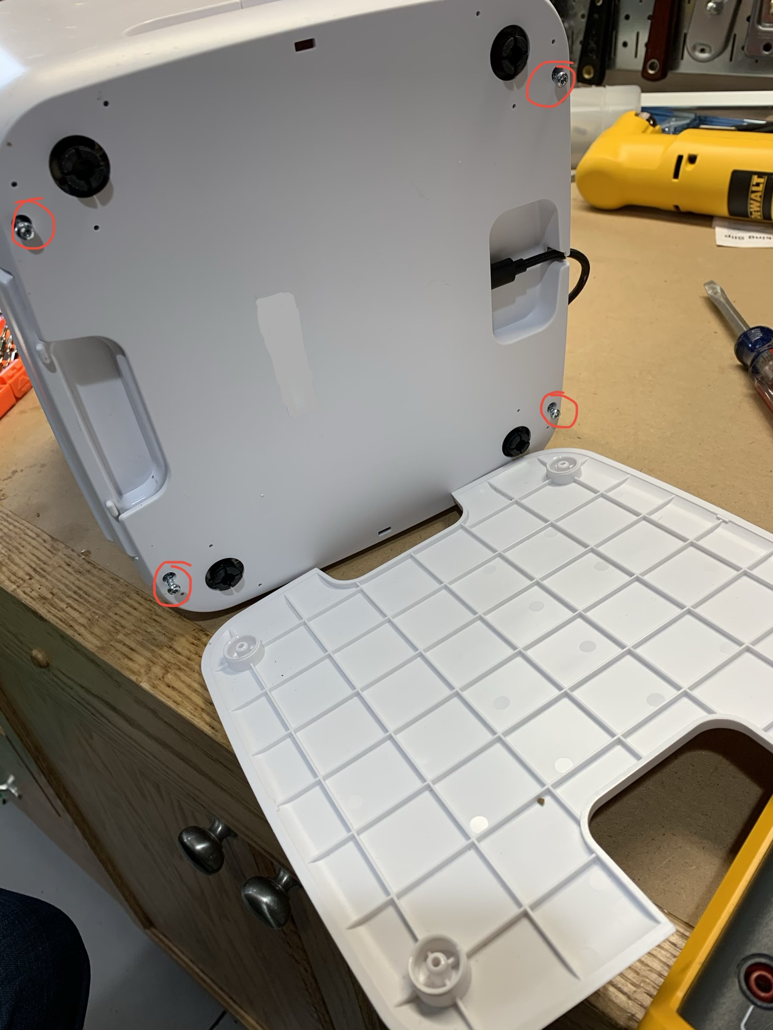
First, you need to pop off the outer shell. All you need is a small pry bar, go into the 4 holes on the bottom, push out and lift up.
Now that the shell is off, you'll be greeted by a bunch of wires, nothing to be scared of, just don't break any of them.
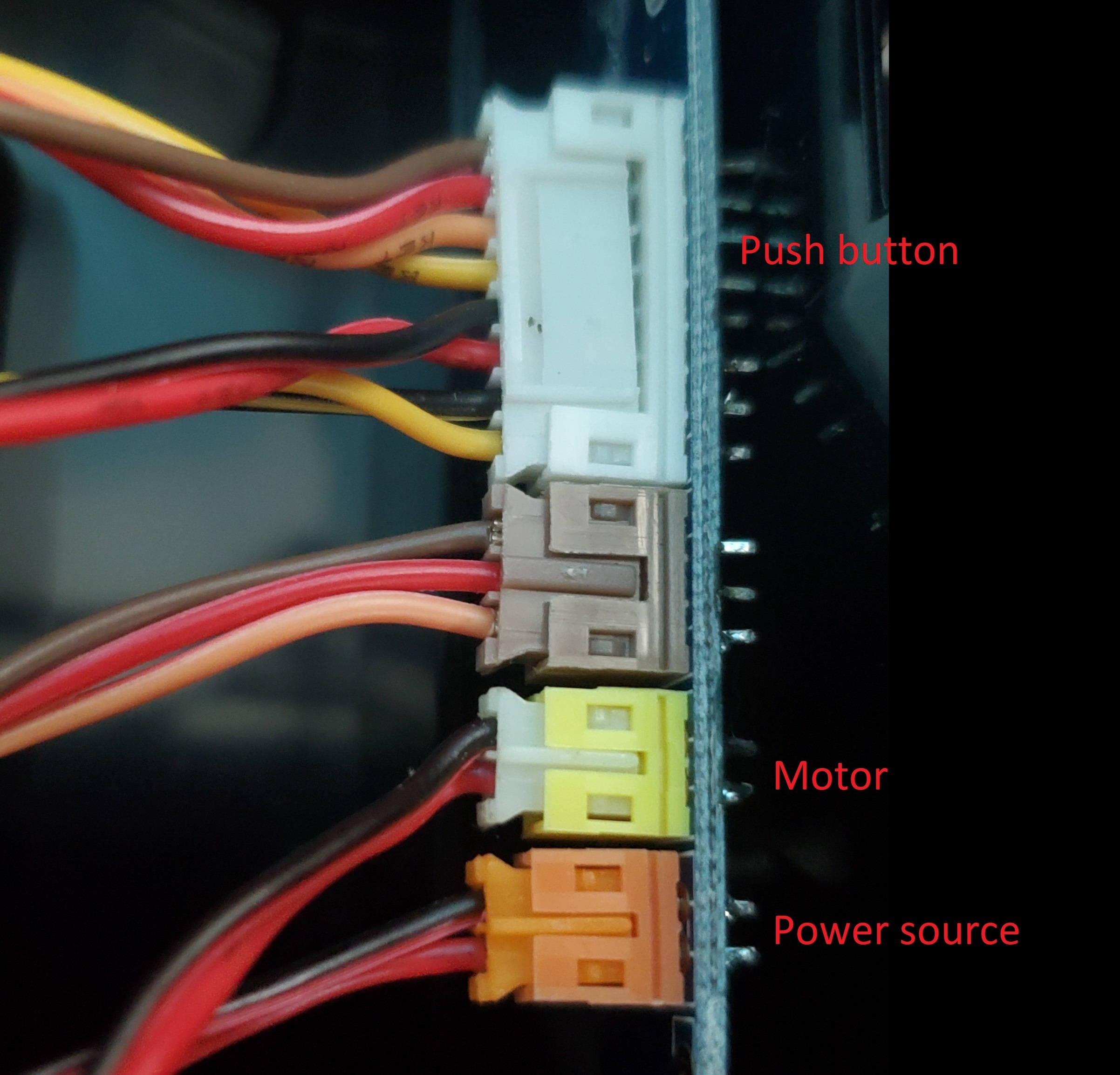
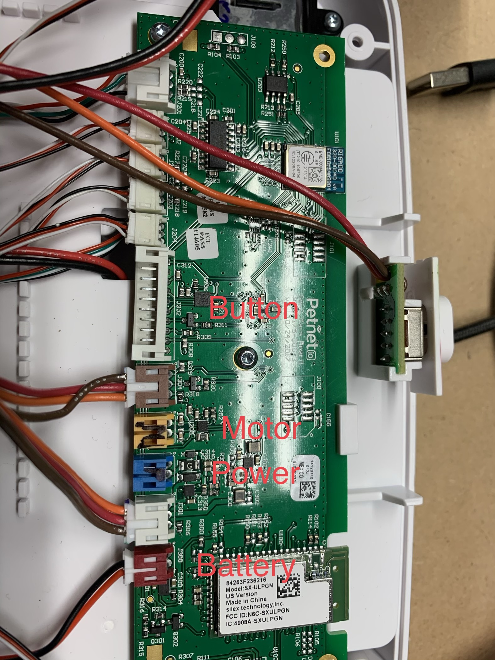
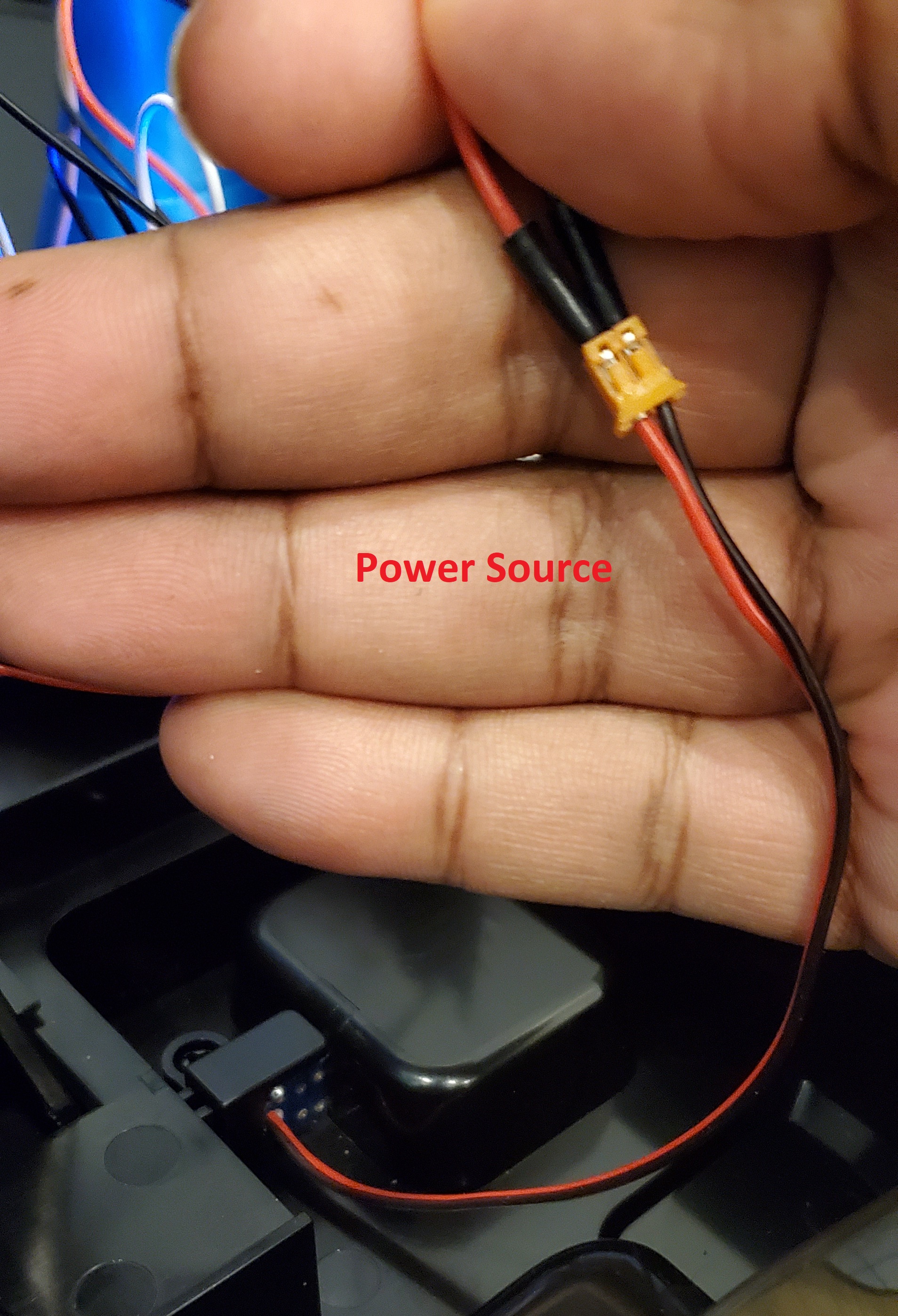
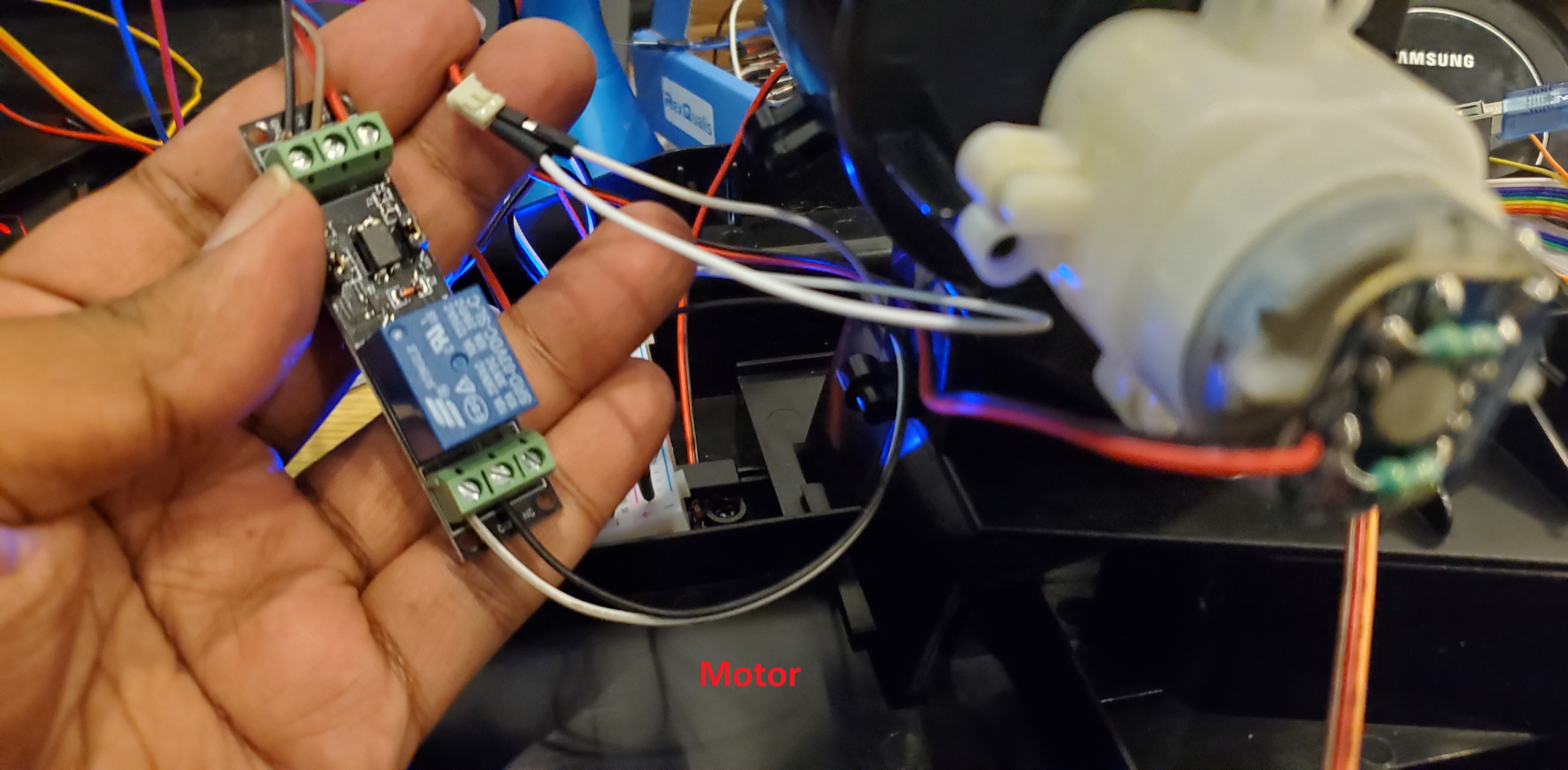
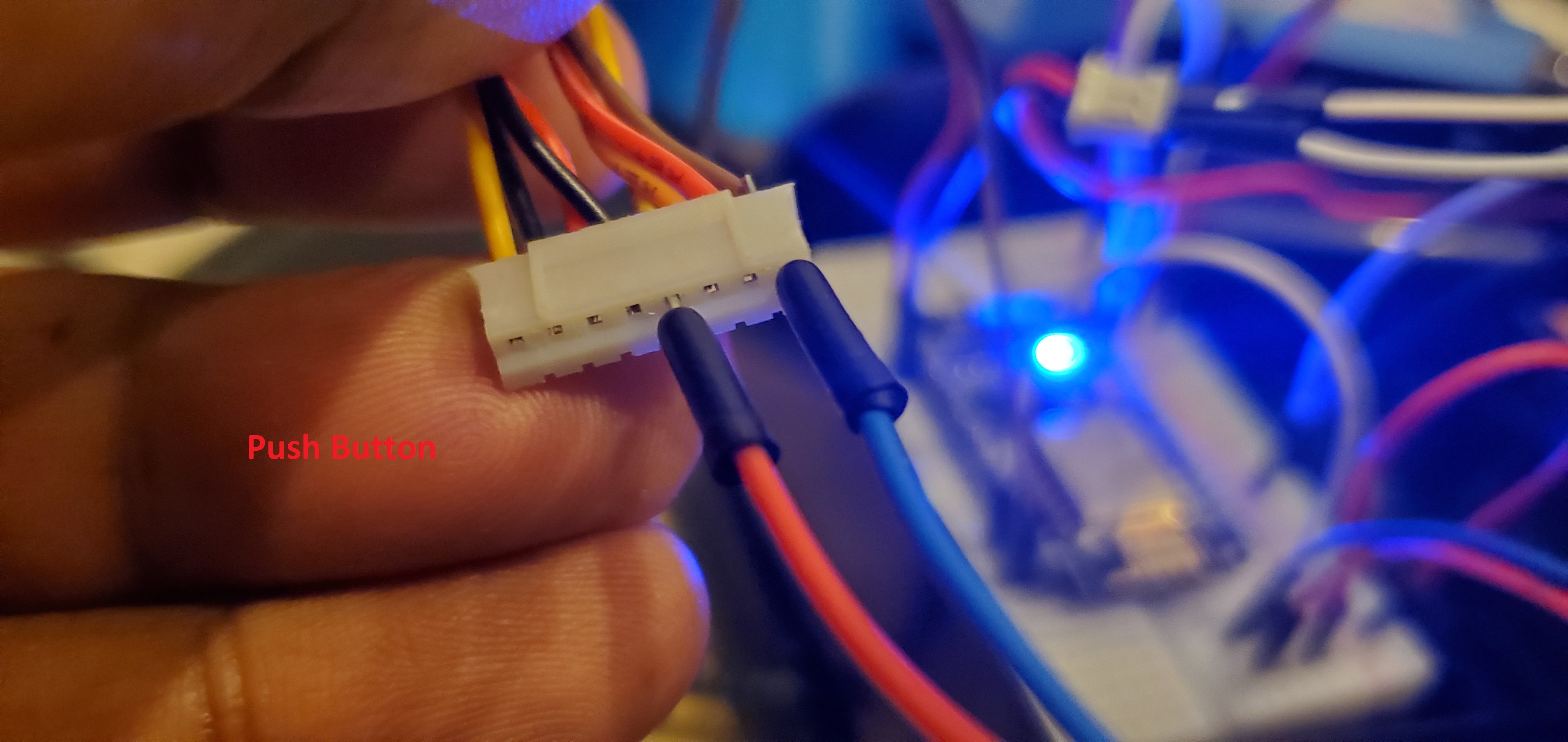
On the board, the wires will be as follows. To control it, all you'll need are the Power Source and Motor, I decided to use the Push Button as well to help keep old functionality.
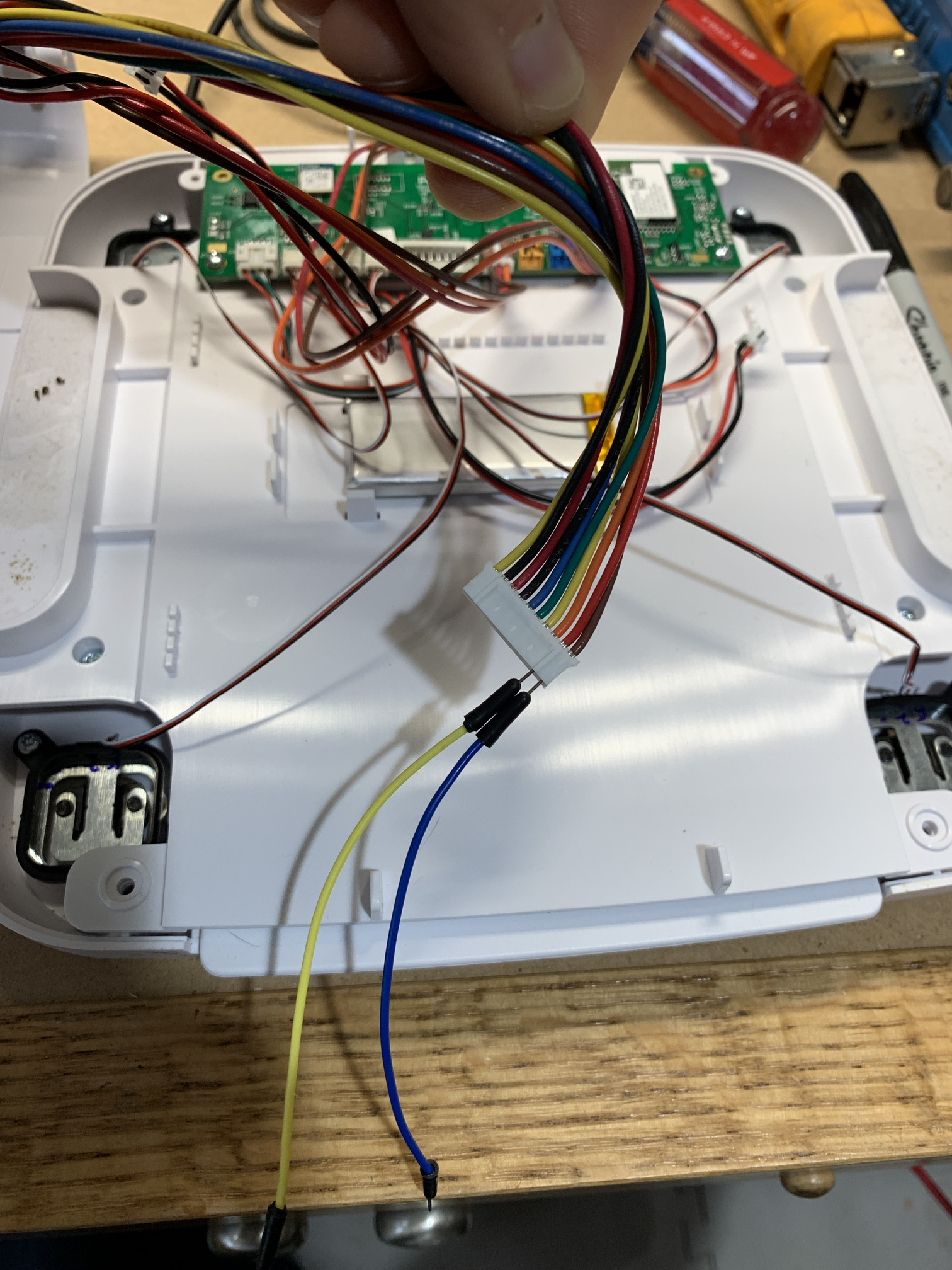
Each of these harnesses can be pulled out and connected directly.
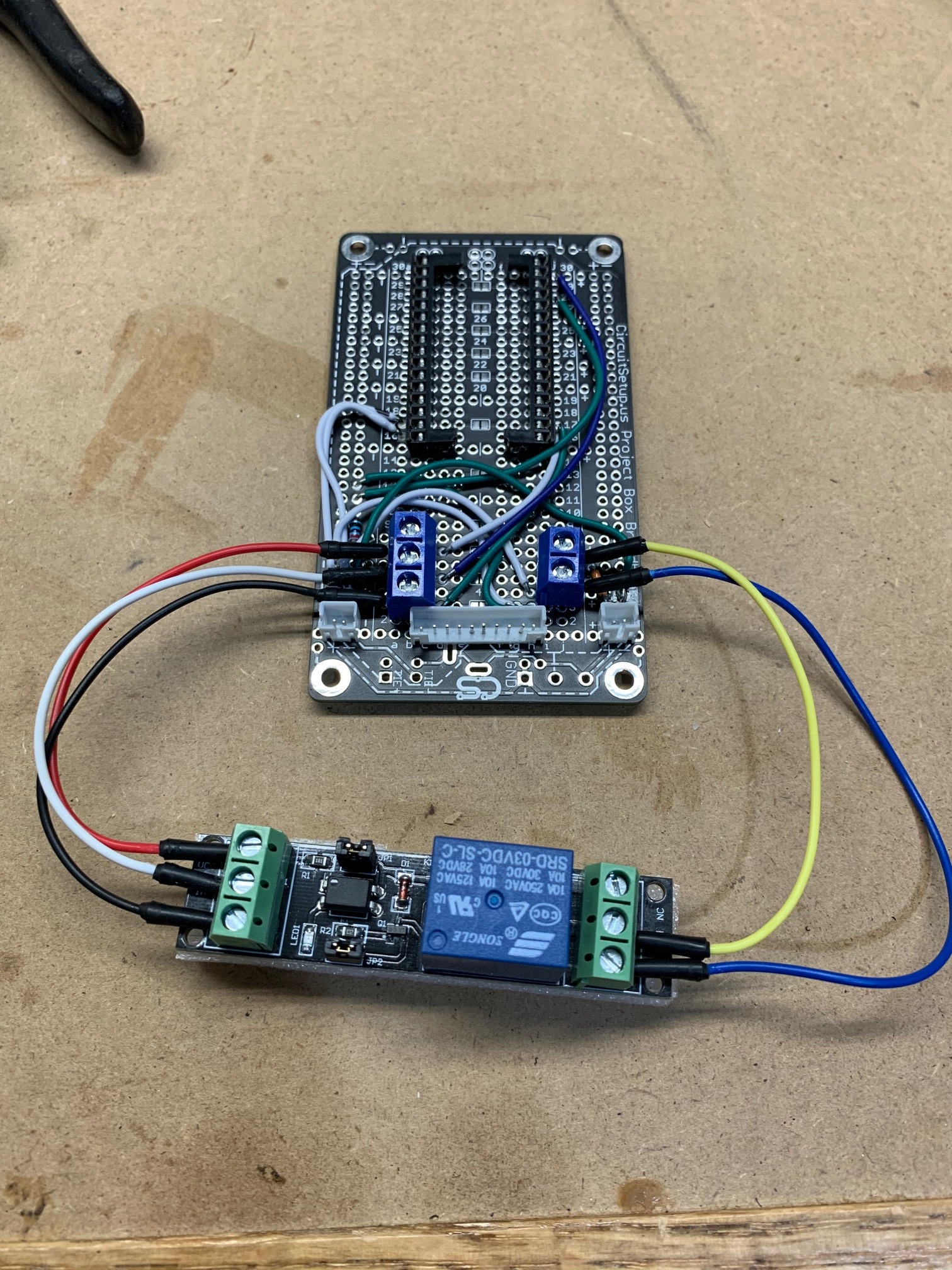
Since the NodeMCU only puts out 3.3V, I used the relay to trigger from the output pin, and pass 5V to the motor to operate.
If you don't care about using the button, it's straight forward (red = positive, black = negative). If you do care about using the button, we'll be using the brown and yellow wires.
Lastly just wire everything up and you'll be good to go.

UPDATE: Connect to D1 and update the code to use D1 to prevent the relay from triggering on bootup. Thanks @SteveZed . i'm not updating the original code to correspond to the wiring diagram above
.================.
CHANGES IN HUBITAT
.================.
To prevent the smart feeder from continuously dispensing food when triggered, I created a rule to turn off the switch after 1 second of it turning on. This turn off time can be adjusted to accommodate more food for your pet.
Since I am using the button, I also created a simple automation to turn the switch on the switch when the button gets pressed.
.================.
PROFIT
.================.
You too can save old hardware by using arduino boards and a little bit of exploration.