Perfect. In my testing ,Peter has fixed the accidental dual activation, where turning on 1 physical switch activates both switches, which are attached to my aqara dual relay.
In my case, The aqara dual relay , with dumb physical switches now properly function, independently I can activate 1 switch without the other also turning on.
Great job @guyeeba, much appreciated
3 Likes
New problem observed. Now EP2 is not working on the local control. But HE control works perfectly. I have suspected the recent platform update and even rolled back to 2.2.0.132 . But unable to restore the old behavior.
Unsupported tag in Xiaomi Report msg: dataTag = 0x9b, type = 0x21, length = 2 bytes, payload = 0000
I am seeing the above error in the debug logs. But I am not sure this is related to the issue.
Do others also seeing the same behavior ?
Thanks and regards,
Pugazhendhi M
Tagging @markus - is this one of your drivers? On my phone, so I’m unable to search effectively.
2 Likes
No, I have not finished my drivers for these yet, not a lot of time lately, this is a driver from @guyeeba.
2 Likes
Hello @gzisimatos, did you manage to make Aqara Relay work fine with two switches 3Way and one 4way in the middle? If I put my original non smart led lamp, it works fine, but the switch port in Aqara relay miss most hits in the middle switch (4way) and some on 3way...
Hi @alexspires , I haven't tested the new driver (that swithes with 1 command the state for both lines) but you should know that in my setup I didn't use S1 or S2 at all (their behaviour was weird when used).
So If I understood well , instead of keeping your existing wiring 3way-4way-3way and put in the middle aqara (which doesn't behave properly) change the initial 3-way with a 4-way and attach aqara L1 and L2 to it (aqara-4way-4way-3way-light) as in the picture in my previous post. Sorry if my help is not enough.
IMHO it is the combination of interlock-driver that makes S1 and S2 seem useless.
Hello guys, I need help as I just burned forth aqara relay. 
I connected it just like it was explained previously in this tread.. And when I connect switch, relay die... Only diference is that I have somfy engines for external shades instead of lights. But still everything works untill I connect switch.
I need advice how to connect wires correctly and if there is possibility to fix relays, buy some part and replace it?
Thanks in advance
Can you post the sketch how did you connected?
I fear, replacing the relay wont be an option as these pcb's are not DIY friendly, unless you have exceptional soldering skills and tools.
Normally, these are not supporting inductive loads optimally. They are designed for the resistive loads. Aeotec is having devices for connecting inductive loads.
Hi all! I'm new here and I have the same problem than @milan_milunovic I have burned/kill three aqara relay. But I have other three working.
The first burned I don't know why when installing, I replaced by another using exactly the same wires and it worked.
The other two that I kill/burned I tried to do a slightly different connection because I don't have access to all the wires from the schema, but I installed thinking that it will be the same.
I don't know too much about electricity/electronics, so if I'm wrong please tell me:
-
If the L and IN are joined internally in the relay, they are all the L line, so the schema from Aqara will be the same than this other from a Shelly 2.5:
photos.app.goo.gl/L3jz9ppXb8z6JDp19
the big difference is that only one of the switches ends are connected to the relay, the other is connected directly to L. This makes it easy to use in my installation but is clear that something is wrong because I burned two of them when acting over the physical switch. Someone can explain? -
Now my second question: I have opened it, is there some "easy" piece that I can replace to make it working again or the damage has been too big and they must go to the trash?
photos.app.goo.gl/wnAuji2fibAZKwde9
photos.app.goo.gl/jjUSGJkV3hcXTe8fA
I have experience soldering, but I don't know too much about electronics...
Thanks again for your time!! I don't want to burn more, and I don't want to use a wifi relay like the Shelly one, I think zigbee are more stable, at least in my case.
Sorry for the links, I tried to put the images directly but I don't have permission to do that, and neither to add links.
One thing more: I'm not too sure, but maybe I have connected the IN of the relay to a different Line than the switches. I have drawn a little paint schema:
photos.app.goo.gl/UuAeDgH8TYqoMqJo7
I didn't have Line in the place where the relay is, I taked from other place, so maybe by error I have taken it from a different Line than the switches. The switches from my "lights" Line, the relay from the "plugs" Line. Can this produce the kill/dead of the relay or this is indifferent?
Thanks again!!!
I think that is possible. In the USA there are 2 separate 120volt lines, and don't think they should be connected together in the relay. See the diagrams earlier in this post
I saw the diagrams, but some things are too complicated for me 
Thanks for your answer, so you think that connect it to different lines, is what break the relay. If I connect the switch to the correct Line, it will work or do I need to connect it to the relay mandatory?
Regards!
If you need a local control, then you can omit s1 and s2 connection altogether and you can control the relays via HE. And this connection is confusing, as noted sometime back, even if you connect s1 to L1 and S2 to L2, when trun on s1 , that will toggle S2.
So this was rectified in the driver later, and now, S2 is not working at all.
But both are controllable via HE. The brightest minds @markus and @guyeeba can bring the best of this device.
Now , the image you reffered is exactly similar to what @Rxich is referred, Circuit vise both are same except he is talking about 120 volts.
In essesence both the loads at one end connects to the neutral and the other end goes to L1 and L2 of the relay. Now the switches wont work but controllable via HE.
Now if you connect the switches to the S1 and S2, that will offer local control. But right now thats having issues and expecting a working driver. .
I hope this helps. And I am not adding anymore confusion.
Yes I believe the problem is the 2 lines connected to relay, are you in the USA 120V or another country with 220V AC?
This circuit is correct one.
As @Rxich mentioned, Another line from another circuit might be an issue, as this might make the potential difference to 440 v . or 240 v depends upon where you are.
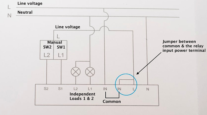
For your reference.
Yes, that is what I thought. I live in Spain/Europe, we use 230V lines, so both lines must be 230V in theory, but is clear that something went wrong when I used both, one for power on the relay and the other for the physical switches.
About the problem with the physical control, as I seen in other places is simply that the S2 and S1 labels are wrong. The S1 controls the L2 and the L2 controls the S1. For the rest, they work perfectly. I have tested them at the bench using zigbee2mqtt and they work perfectly, physical and digital, with interlock enabled and disabled.
I have ordered one new, I will try again in some days this time connecting both to the same line, and I will report.
1 Like
The function of the physical buttons/switches can be set independently, and in the latest version of my driver the aforementioned "interlock" function works properly (it was buggy previously, so a press on "Save preferences" might or might not be needed).
But for the sake of completeness (and to save some time for @markus ![]() ) there are comments in the source code of my driver about the values needed to control these functions, so everyone can make their wildest dream come true with some tweaking on the driver - as long as those dreams are related to S1 and/or S2.
) there are comments in the source code of my driver about the values needed to control these functions, so everyone can make their wildest dream come true with some tweaking on the driver - as long as those dreams are related to S1 and/or S2. ![]()
3 Likes
Yes, many thanks for those comments, I seem to not get it right though, I have one of them here and will fix it soon ![]()
1 Like
Hang on guys, Guyeeba's driver works fine for me. I have independent control over both switches, physical & digital, with both S1 & S2 connected
--tried to post driver but formatting gets all screwed up

