Does anyone have a suggestion on how to automate a Panasonic Whisper Comfort FV-04 spot ERV? It is in an area that is sometimes unoccupied, so I would like to automate its "off" and "on" switch to be tied to a motion sensor in the area.
The challenges are:
The existing wall switch for this ERV is a single gang stacked, double wall switch. The top switch turns the unit "on" and "off", the bottom switch toggles the fan between high and low.
The wall top switch is actually an on / standby switch, rather than an on / off switch, and per the manual the unit still uses power when the wall switch is presumably off but really in standby. Thus, I am not sure if the wires to the switch actually have line voltage.
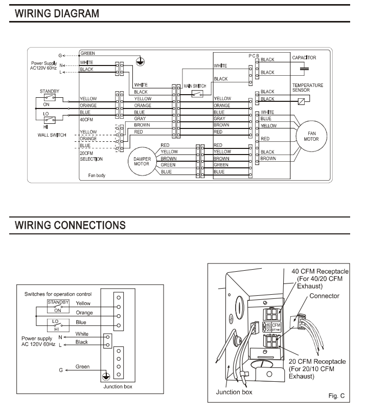
This is the wiring diagram from Panasonic:
The two switches on the left side of this diagram are the wall switches. The switch labeled "Main Switch" is internal to the unit and not something I will mess with.
The single gang double wall switch is in a double gang box with a light switch, so I think there is a load line available in the box.
In addition to automating the on/off, the ERV on/standby switch still needs to allow manual on and off, and obviously the low/high switch needs to work manually. I don't have any need to automate the low/high switch. Either Zwave or Zigbee would be fine.
The main challenge you will be up against is making sure the smart switch can handle the load requirements. Fans pull more voltage to start the motor. There are double relay options too that you could hook up to the existing double switch you have and tuck the smart relay in the back of the gang box. But again many don’t support the load requirements of a fan motor.
Thank you
A bit more info found in Panasonic documentation:
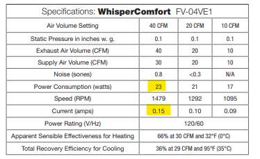
Max power consumption is 24 watts (some docs state 23), and current is 0.15 amps, both when fan operates on highest cfm.
I think the wires to the double switch are CONTROL wires, and do NOT have line power on them, due to both the wiring diagram note over these switches stating "Switches for operation control" and this note in the service manual:
"Do not connect the control lead wire to the power supply"
Thank you! Can you please help me understand how it would work?
This thing looks wayyyy too big to go into the box the switches are in. I'm not sure there is anywhere to install this...the line load terminates in a box that is part of the unit and even smaller than the j box for the switches and hardly accessible. Is there something like this that can fit in the box behind the switches?
It says it has three relays. I only need to control the on / standby (off) switch, so do I need this multirelay?
It says the three relays are 20 amp and two 15 amp and for any 12-120v load. I think the wires going to the switches are control wires, so not sure if their load is at least 12v. I've scoured the data sheet, the install manual and all other info I can find about this but I can't find the voltage for the control wiring anywhere. Are such controls usually at least 12v?
If I did manage to get this or something similar installed behind the switch, is there a way to wire it so the existing dumb switch still works?
Thanks
Hard to say without knowing more about your installation. You could consider cutting the control wire wherever is convenient and not a fire hazard and install the relay there. Keep in mind the smart relay needs (usually DC) power. If there's power in the box, you can replace the dumb switch with a smart one and link it to the relay through HE.
The ZEN16 is great. I use a similar ZEN17 for one HRV (+ other stuff) and a cheap Zigbee MHCOZY single channel relay for the other. There are two and four channel versions of that relay. Keep in mind you might eventually change your mind and want to automate both on/off and fan speed.
Shouldn't be an issue at all for HVAC control wires. However if you own a multimeter, you can check this stuff pretty easily. Check the voltage across the switch when open. Then, with the multimeter in series with the switch, check the current when the switch is closed.
IDK about these standalone, single-room units but typically E/HRVs are designed to have multiple controls attached to the same terminals (say, one on each of two floors, or a bathroom control to switch the fan to high speed). You should be able to set up the relay and the switch in parallel (either closed = fan ON, or high-speed). I recommend you confirm this with the manufacturer first.
The ERV is installed in the wall. There is power to the ERV that terminates in a small J-box attached to the ERV. That J-box is accessible through the inside of the ERV, but barely. That J box is also where the ERV control wires come out, and the electricians connected romex to those, and ran the romex to a wall box. It is a two gang wall box - one side is a switch for the nearby light, the other side is a double paddle switch to control the ERV.
I'm fine giving up the opportunity to automate the speed. It is never on at low speed anyway. I think I need either a device that will fit in the box behind the switch, or an actual double paddle switch replacement. Not really anywhere else to install it, and neither is there anywhere aesthetically acceptable to install a box with a blank cover...
I own a multimeter, just need to learn more about how to use it. I'll google how to do this...
I'm fairly sure this spot ERV is not intended to have multiple controls, as evidenced by the wiring diagram posted above...there is only one set of control wires. The switch on the wall is just a standard two paddle single switch the electrician installed. I'll contact the mfg to see if they have a suggestion and post back...
If so, can you provide a bit more info? It looks like you might have the on/standby and the fan speed switches each as a single switch, which would make this easier, but maybe you don't... I'm only looking to automate the on/standby switch, and mine was installed with a one gang double paddle - on/standby on top, low/high fan below.
I had power to the unit automated using a GE zwave switch, and then an LFM20 relay (dry contact relay) to toggle hi/low speed. That's it. In retrospect, I wouldn't bother with the high low speed unless you're covering a very small space (as on high, it's only 30 CFM fresh air supply). I removed the unit as 30 CFM was not enough for a family of four, and at cold temps (below -7 C) the unit spent most of it's time in exhaust mode only which made the problem worse. I've replaced it with this setup which can vary between 50, 60, 75 and 90 CFM at a much higher efficiency than the small Panasonic spot ERV: Success! 0-10 Volt Control of AC Infinity (or any EC fan motor) using Leviton ZS057-D0Z Zigbee Dimmer or Zooz Zen54 zWave 0-10V dimmer
So did you have the on/standby and the high/low on separate switches?
Does the GE zwave switch need line power to work, and if so, does the GE zwave separate that incoming line power from the controls? It is my understanding the controls wiring, including the on/standby, are not line power.
I had power to the unit wired via a GE zwave wall switch..this switch would cut all power to the unit, so is not the best way to do this if you want to make sure that the intake damper closes correctly if powered off. Separate wires ran from the ERV to an LFM20 dry contact zwave relay to toggle high/low speed. Doing it again, I'd run power to the ERV, and then use a dual contact relay like the Zen16 ( Zooz ZEN16 MultiRelay – ZOOZ ) which would let you manage both standby mode, and high/low speeds. Hope that makes sense.
I use a Zen16 for my garage door automation and it's a reliable piece of kit.
A few questions:
What size of space (approx. square feet) are you ventilating with the Panasonic?
How many occupants?
What climate zone are you in?
Is this unit going into a basement space?
I have three air quality sensors (basement, 1st floor, 2nd floor) in our home now and I've learned a lot about radon, VOC and Co2 levels and how they correspond to occupancy, ventilation etc. I suspect you may want to leave your ERV running 24/7 based on my research/observations so far.
@denwood: Thank you. You are exactly correct - I want to control the control wiring on/standby switch, and NOT control the power to the unit. @user3352 also suggested the Zooz Zen16, but I just don't have anywhere to install that thing. Installing a box with a blank cover on either side of the wall between the ERV and the switch is going to have a HAF of 0. I do not have any room to make the existing box with the switches larger because inside the wall there is stud on one side and the rigid 4" ERV duct on the other side of the box. So is there ANY zigbee or zwave double paddle switch for this use case that could replace the dumb double paddle switch, or a relay that can be wired in behind the dumb double paddle switch in that j-box to control only the on/standby switch?
As to your questions:
Size of space: The FV-04 (already installed by the builder) I am trying to automate ventilates an area of the house about 550-600 sf. There is another ERV for the constantly used part of the house; I don't need to automate that as it runs continuously 24/7.
Occupants: This is exactly why I want to automate this ERV. There are times this space has no occupants for several days at a time; most of the other time it is only one occupant.
Climate Zone: The one Panasonic lists as ideal for the FV-04
Space unit is going in: Unit is already installed, and no it is not a basement.
Not on your list of questions, but I also have a bunch of sensors, including Airthings, to monitor radon, Co2, etc. But running the ERV I'm trying to automate 24/7 is definitely not needed when that space is not occupied. That space has its own HVAC system, with its own return across from the ERV, so there is no chance that even the HVAC system would mix air from that ERV into the balance of the house. Running this ERV has no measurable impact on air quality in the always occupied parts of the house.
ETA: Per Panasonic, the control wiring CANNOT be connected to a load, but neither is it Low Voltage. They said it is about 100 v. They also confirmed the on/standby switch can be "wired in parallel to a dry contact or a relay." They recommend a dry contact.
So does anyone make a UL rated zwave/zigbee double paddle with dry contacts for both paddles, or 1 paddle dry contact, 1 paddle dumb switch?
Or a very small dry contact I can install behind the top paddle of the dumb switch?
Is yours UL rated? One post on Amazon claims it is, but there is no such info on Aeotec site.
The dual does not seem to be available anymore for North America...
Are you able to share the wiring diagram of how you did this? It says it requires a neutral...which one of the control wires is the neutral (yellow, orange, blue?)
NGL, I did not read the entire thread. The Yellow/Orange/Blue wires look like they are just switch loops so no neutral and you also said they are a reduced voltage (I would suspect they are actually 12-24v).
That being said, a ZEN51 would be able to switch it BUT you line voltage to power it. Not sure if you could wire it where the control module is instead instead of in the wall? You would have access to line voltage there. The IN/OUT on the ZEN51 is a relay of some sort. Possibly the ZEN52 (double) could also work but I would have to confirm if the outputs are tied to the S1/2 or the L 120v input. To fit the double into the same small housing it does not have dedicated inputs like the ZEN51.
I would install the Zooz zen16 at the ERV (it’s very compact) and run low voltage lines to a standard dual paddle single gang switch. The zooz can take switch inputs (no voltage, just open and close) to control the relays. You can also set up those switch inputs as momentary switches which might work better to just toggle the relay state each time they are pressed. That would give you both manual and automatic control. You need isolated relays for both circuits to the ERV controls. Devices like the nano and zen51 won’t work as they are designed to power a 120V device via line and load…they would cook your ERV controls.
Panasonic ERVs are a bit weird as I’m pretty sure they all use 120V at the control wiring…it has come up at the green building journal quite a few times.
Based on all the information you provided, yes, you’ll see some benefit from automation :-). I’ve found that turning off our whole house system (which happens when co2 levels averaged over 3 CO2 sensors goes below 450 ppm) when we’re away, can result in elevated radon levels in the basement. I’ve changed the automation rules around co2 a bit so the system just stays at the base ventilation rate of 50 CFM longer. It basically has 4 balanced profiles at 50,60,75 and 90 CFM. Hubitat manages the two EC fans on the HRV to those profiles depending on the 3 AQ sensor readings for CO2 and VOC. There’s a fifth profile that manages make up air for the kitchen exhaust via the HRV.
I would install the Zooz zen16 at the ERV (it’s very compact) and run low voltage lines to a standard dual paddle single gang switch.
Thank you. I really appreciate you taking the time to reply because you seem to really understand this stuff (I understand enough to get in a lot of trouble) AND you have first hand experience with the Panasonic FV-04. Per your advice, I will stay away from the Zen51 and the Nano, as I have ZERO interest in damaging the ERV controls. I greatly appreciate the heads up!
The ERV is wall mounted, with finish gyp both sides of the wall. I cannot fathom where I would install the Zen 16, nor how I would get the required USB or 12-24v power supply to it that the Smartest Home site says it needs...When you say "install at the ERV" do you mean inside the ERV housing? I'd be concerned about having exposed 100 or 120v wiring for the Zen16, and no idea how I would power it if installed in the ERV.
The only install location I can come up with is the attic above the ERV, where there is a power source for it and plenty of space to put it in a box. But that mean fishing wire from the attic to the ERV Jbox, and back down, with connections in the very difficult to access ERV jbox. That is probably doable, but it is a MUCH larger project than I can embark on now. Was really hoping for something I could either install behind the wall switches or replace the switches with...
I have no idea how the ZEN51 could damage anything, it has a switch that triggers a open/close relay similar to the ZEN16/17. That being said, I do think the ZEN16 or ZEN17 is a better fit for this application.
I think the issue with the Zen51 is that the dry contact relay takes signal from a switch, which in turn passes power to a light for example via the 120V LINE, LOAD connections, which also power the Zen51. This is not an isolated dry contact relay as the switch signal is 0 volts...just open/close.
If there is a way to wire the Zen51 to 120V, and have a completely isolated relay that is ok with 120V, then you could use it...I just did not see the wiring diagram use case for this on their site. Looking at the Zen51 wiring diagram, it looks like OUT will pass 120V to the device when the relay is energized, via the L terminal (which also powers the Zen51)...and the load device would need a connection to neutral. I can't see how you could use this with the Panasonic control...
With the Zen16, you command the dry contact relay on/off via automation, or a switch connected to the switch ports. The device is powered separately via USB and none of the relays/switches need to see LINE/LOAD connections from 120V. The relays can pass power up to 15 amps, but they don't use 120V to power themselves, and don't need a neutral connection.
I may have my wires crossed, but I've always used relays like the LFM20 and ZEN16 for these control applications, and devices like the Aeotec Mini, Zen51 to power lights via 120V in the box.