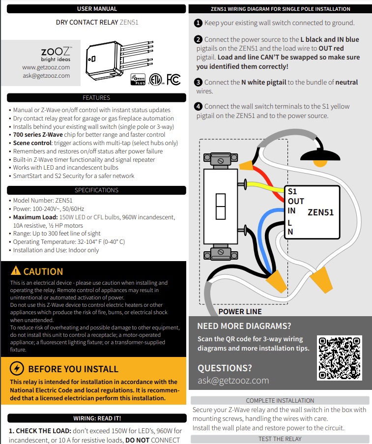
I don't think this is the case. The L and N leads are to power the device/relay only and the IN/OUT leads are dry. To power a light using this device, one needs to make it "wet" by connecting IN to L and OUT to the load, as shown in the wiring diagram Zooz provides. The S is indeed line-switched. I believe it is designed this way to simplify a three-way setup for a typical lighting application. You don't have to use S.
In contrast, the ZEN52 double-relay version doesn't have independent inputs so one should assume that the input on the load side of the relay is wired to L internally.
That makes sense...I was trying to figure though why the physical switch is pig tailed to the hot. If IN/OUT is a separate relay, then you are correct in that this device x 2 would work for the ERV control.
I've asked TheSmartestHouse.com about the Zen51 dry contacts. Will update when I get a response
I saw this on the Zen16 vs Zen17 page: "The switch inputs on ZEN16 are dry contact only which means you can't connect any voltage to them"
a. So I would wire direct from the two dumb switches to two of the the Zen 16 switch inputs and it has no voltage? If so, can I use the approx 7' long 3 conductor (BWR + ground) Romex that is already run or do I need new wiring? If I cannot use the Romex wiring already in the wall to the switches, this turns into a project with drywall work and ZERO HAF even with the Zen16 installed in the attic.
b. Then I would connect the ERV control wiring, which Panasonic Tech Support support stated is 100v, to the R1 & R2 ports of the Zen 16?
I was thinking maybe it was on the S1/2 inputs but I think you are right it is on the L, because it can be used without the switch connected. So yes ZEN52 can only be used for line voltage, fans or lights typically. The ZEN51 should work for just about anything but depending on the type of relay not sure how much of a load it can handle.
*Should also note I have both of these on my test "bench" (piece of cardboard on top of some bins) right behind me if there is anything I can test out. I only have a multimeter though, nothing too fancy.
@jtp10181@denwood@hubitrep
I just received an email from thesmartesthouse.com (Zooz sellers) about the Z51 stating:
"Yes, ZEN51 is a dry contact relay. The ZEN51 needs 120VAC to be powered on L and N pigtails, so you would need to power up ZEN51 from [the light switch also in that box but on a different circuit]
Then IN and OUT pigtails is a dry contact relay. Totally isolated from L and N pigtails."
So I'm going to order 2 and see if I can make this work...and pray I don't blow up the Panasonic controls...
Please let me know if you see any problem with this plan....
@calinatl , I think you're good there. If in doubt, just wire it up (don't connect the ERV to IN/OUT) and check voltage across IN/OUT. It should be zero as you toggle the relay on/off via Hubitat. Based on that reply you got, and what @jtp10181 has said already, I'm about 99% confident you are ok. This information is good to know as I may use this in future projects. Powering from 120V is a lot easier in many situations. This is basically a nice replacement for the LFM20, which was unreliable and about six times the size.
Glad to help (and get educated on a new relay option too). The Zen16 is great, but the external power requirement makes integrating into an existing box quite difficult.
Thanks to @hubitrep and @jtp10181 for setting me straight on this device
Was able to wire this up with two Zen51's. Zooz support was very helpful and gave specific directions. They confirmed that not only are the IN and OUT pigtails a dry contact relay totally isolated from L and N pigtails, they later confirmed the IN and OUT pigtails are also isolated from the S pigtail.
It was a bit a difficult to fit two Zen51's in the box, but managed to do it.
So far it seems to work great. The ERV can now be controlled from either Hubitat or from the wall switches - both work equally well.
ETA: thanks to @hubitrep and @denwood and @jtp10181 and the others who contributed to the above discussion. Not only did it help me automate the Panasonic ERV to be able to control it with Hubitat, I also learned from the discussion. Much appreciated!
Per post 27 above, I got this wired up and initially I could control the ERV from either the wall switch or the Hubitat.
Suddenly it stopped working from the wall switch. I have definitely not rewired anything, and I don't think I changed any of the parameters. Does anyone have any idea what could cause this, and more importantly, how to fix it?
If you are using my driver turn on debug or trace logging. If the device is sending any messages they will get logged. Also check the connections, maybe something came loose?
@jtp10181
I don't think I'm using your driver. On the device page, under type, I selected "Zooz Zen51 Dry Contact Relay" since that matches the hardware.
Re: checking connections - do you mean the physical wiring connections in the box?
That is the system driver you are using, you could turn on debug logging there see if you get anything. Not sure if all the settings are exposed on the system driver, but you could always try mine to confirm all the settings: [DRIVER] Zooz Relays Advanced (ZEN16, ZEN17, ZEN51, ZEN52)
Another follow up to this post.
The two Zen 51's are working great to control the two functions of the dumb double paddle switch
Standby/On
Hi/Low
The challenge is the switch positions. The automation rules are fairly good at turning the ERV on and off, but then the buttons on the dumb single gang dual switch don't match the positions I've trained my household on. While it seems intuitive to me that if the ERV is totally silent, it is off, no matter where the switch is, others in my household think if the switch position is where they were trained for the unit to be on, "it is just operating very quietly today."
In addition to the retraining of my household, which is under way, I'm aware of three other potential solutions but would appreciate some feedback
Totally automate this so switches are never used so the physical position of the switch does not matter. Working on this (see below) but not sure it is attainable.
Replace the single gang regular dual switch (maintained contact?) with a single gang momentary dual switch. After much googling, I've found a Legrand Pass & Seymour TM811-DTMOW that might work - just not sure because the spec sheet calls is a "Double Throw Momentary Contact." Doesn't double throw mean that if one is on, the other is off? So every time I put the speed on high, the standby/on would immediately go to standby? Or am I reading too much into this? Spec Grade Decorator Momentary Contact Switch
If this switch is not correct, does anyone have a link to the existence of a Code Compliant single gang, double switch where both are momentary?
Both 1 and 2 above, which would be ideal, but might be overkill.
With the two Zen51's, the box is tight. Not sure if a momentary switch would be deeper and thus take up more space than the standard big box store single gang dual paddle in there now. To make it fit, I could remove the Zen 51 controlling the Hi/Low fans speed which would free up some space in the box, but it turns out to be somewhat useful.
The switch you linked to, I am not sure what is going on there. It looks like maybe the top/bottom are split and they are both basically buttons. Since it says it is momentary and a DT it should basically act like two buttons. When you press and hold the top , the top contact is closed, when you let go it opens. Same would happen on the bottom.
@jtp10181
Yes, what I have now is a double paddle in the space of one switch. But they are manual switches so they hold their position. So a family member might turn the top switch from Standby to On, but then the Zen51 turns it off. The person goes back the next day and sees the switch in what they understand to be the On position, even though the ERV is now off. And to manually turn it on, they have to flip the switch from the on position, to the off and then back to the on.
Same with the bottom switch, except that one is just fan speed.
You wrote
"when you press and hold...the contact is closed, when you let go it opens."
Perhaps I don't understand what momentary means. I thought switches like the Inovelli are momentary for their on / off function, because you press up and it goes on, but the physical switch goes back to a neutral position. You don't have to hold it. The advantage is there is no physical indication of whether the switch is on or off. I'm looking for that same function but with two switches in one "slot"...
They are in a sense momentary because when you press the paddle is it pushing a button on the board behind the paddle, but the switch firmware turns it into a maintained state switch since when you let go the contact stays ON or OFF.
Momentary switches as I said, will close the switch when you press it and then it opens again when you let go. You can set the ZEN51 to work with this and I think it may work well for you. Instead of a paddle switch you would basically have two buttons that when pressed would toggle the state. So you would not be able to see the current state from the switch at all.
Thinking about it, if you do have regular paddles on there now the options 2 for the switch type should work OK. In theory that should keep your on/off switch working the same as it did before except that it may not always be in the same state as the ERV. But on should always be On and off/standby should always be off. Maybe that is how its working and the state difference is the only problem?
Parameter 7: Choose the type of wall switch connected to the relay and its on/off behavior. Values: 0 – toggle switch (device changes status when switch changes status); 1 – momentary switch (one-button switch like the ZAC99; 2 – toggle switch with fixed actions (always toggle up for on, always toggle down for off); 3 – 3-way impulse control (for selected 3-way scenarios, refer to the notes in the wiring instructions for your set-up); 4 – garage door mode (simulates a momentary push button switch in the Z-Wave interface, used for garage door opener applications). Default: 2.
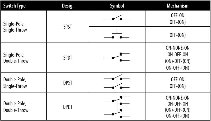
I reviewed the wiring you posted on the first post and it looks like the switch you have now is basically just a double stacked SPST (Single pole single throw). Which SPST is the same as a regular old dumb light switch.
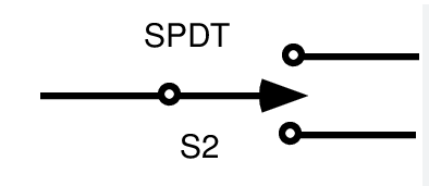
The DTCO switch I found would work like the SPDT except when you let go of the switch it would return to the central off position, where no contact is made.
What about visual feedback, e.g. a dimmable night light or smart bulb tracking the state of the ERV ?
There should be a way to wire the SPST dumb dual switch / set up the automation so a change of position at the switch always toggles the corresponding operational setting of the ERV.
You could use a CO2 monitor for this purpose. What commercial HVAC systems use to drive dampers.
Had not thought of that. Nice idea! I like it because it gets right to the heart of the purpose of the ERV which is sufficient CO2, and ignores all other noise. All these other things are secondary to the CO2. I presume that if the area is unoccupied, CO2 remains relatively stable? I would not want high CO2 readings to trigger the ERV when the area is not occupied as that would be wasteful.
Any recommendations on a CO2 sensor?
I found this Zigbee one from Titian - not cheap...
Thanks! Yes the switch I have now is a regular dumb old light switch except stacked with two switches where there is usually just one.
If I understand correctly,
In parameter 7 of the Zen51, I could change how the existing switches behave, so if the switch is toggled to the position understood as on, but the automation then shuts it off, it would not need to be flipped to off then back to on in order to turn it on? The switch would operate similar to a 3 way switch which has no particular position for off on - just flip it different from what it is now to change the state from what it is now?
The switch you linked only has one paddle. Pressing it up toggles the on/off. Pressing it down toggles the high/low of the fan?
And the "press and hold" does not apply because that is a setting taken care of in the Parameters?
Yes, if you want to do that you would set it to setting 0 Toggle Switch mode. In that mode whenever the paddle changes positions it toggles the ZEN51 regardless of the paddle position or the ZEN51 current state. So yes it acts like a 3-way setup where the switch position is irrelevant.
Yes I believe that is how it will work from the description. It would have two output connections, one could go to each zen51 and then you configure the input as a momentary switch. Each time you press it, it would toggle the zen51 state. I think the one you found might be similar as well it just has a different paddle style that is broken into two buttons. I believe you can even get held/release scene events from the ZEN51 when using a momentary switch, if needed.
Keeping the existing double stacked switch with toggle mode might be more intuitive than the switch I found.