I’m waiting for my Switchmate to arrive from eBay, hard to get hold of in the UK... but I think this could be a perfect solution for me.
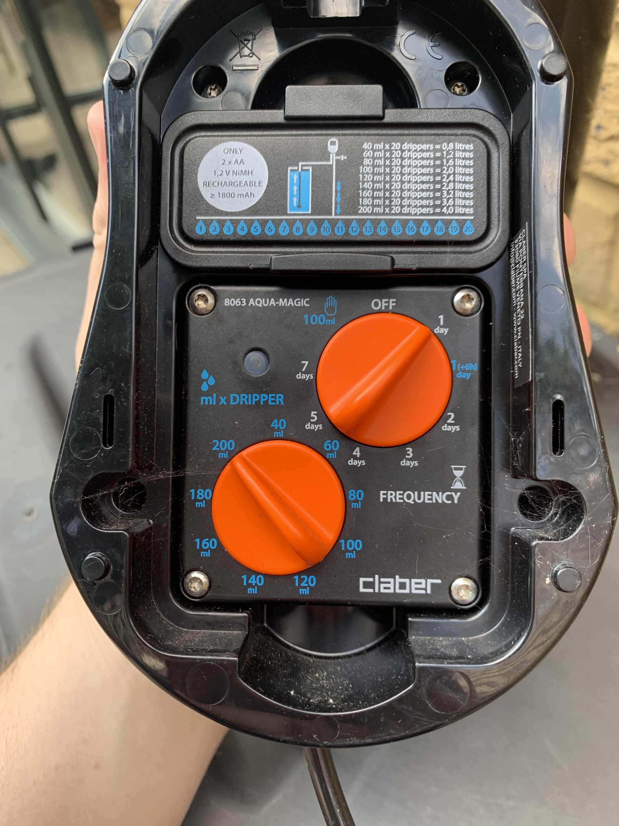
Going back to my original use case of controlling a battery powered water timer, the controls for this include a dial and one of the positions turns the timer on once and runs for set time and then do nothing until it’s turned back to the off position and then back to manual. So by setting the timer to this mode and then intercepting the battery circuit and turning it off and back on again it will kick off the watering! The timer itself has chargeable batteries and a solar panel to trickle charge them so I won’t even need to faff with figuring the circuitry for this out as turning the watering on will just cut the power then reinstate and keep the battery circuit closed..
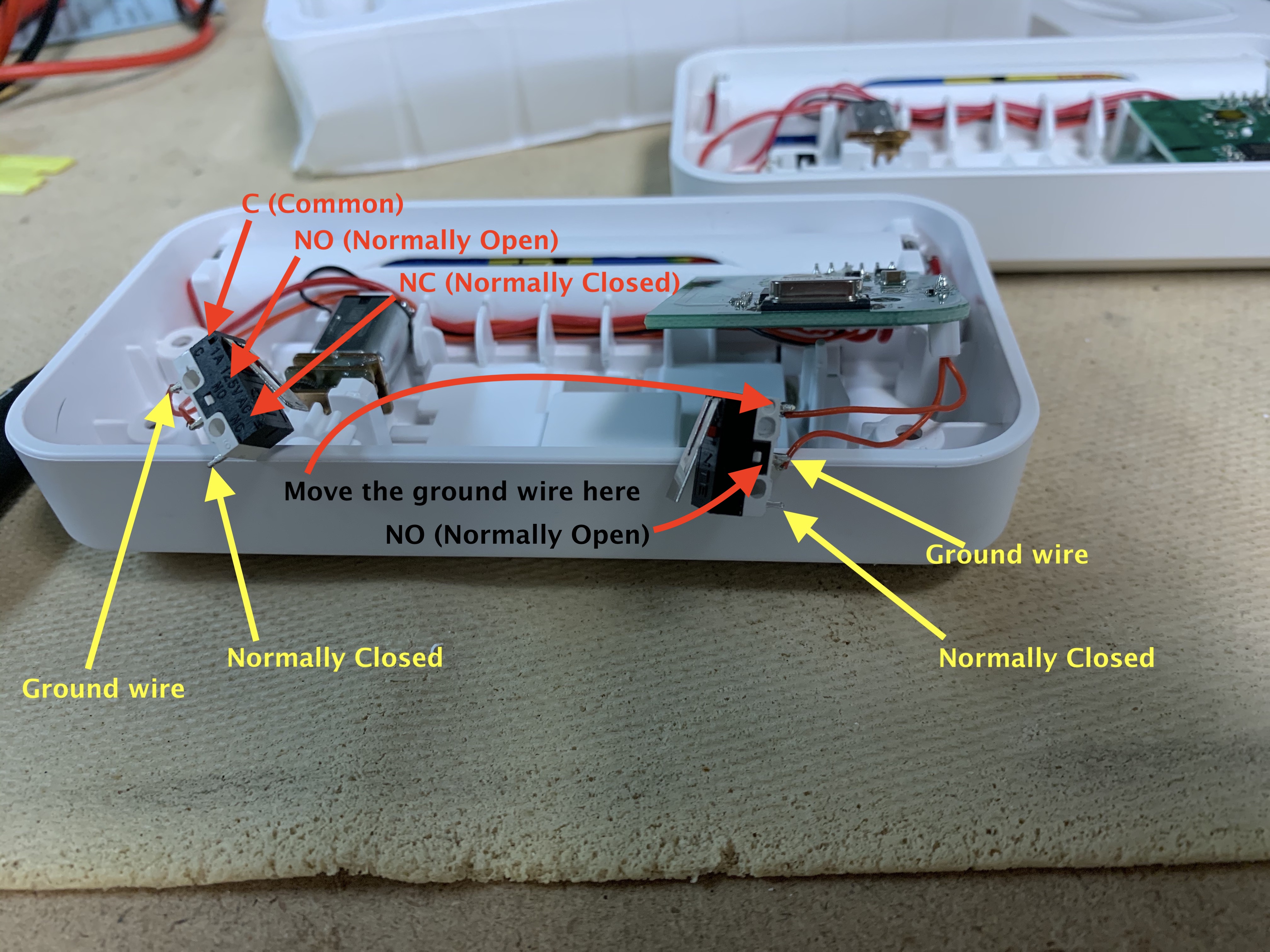
Sounds like you are talking about an entirely different product, so this may be a moot point, but for anyone that is considering using the Switchmate product. Here's more detail on the limit switch wiring.
Essentially, you want the wires that share the same common connection point to be on the common terminal of the limit switch. Since you'd be using the open terminal of the limit switch to close a circuit outside of the Switchmate internal circuit, you wouldn't have the full 3 volts like you do when the switch is close and you measure across the NO and C terminals, but there could be stray voltage going to the external device for which you are trying to close a contact, if the switch isn't wired correctly. In some cases it will be correct, but you have to test that with a multimeter to see which wires are connected together between the two switches, and are they both on the C (Common) terminal or not.
Perfect thanks for the clarification and drawing. I updated my rather garbled post for clarity. But plan is to wire up the switchmate to the battery holder of a water time in the same way you have done for the light.
I understand now. If you’re only using one of the limit switches like I did for the light, then there’s no need to change the wiring around if the common and normally open wires are soldered correctly, as they are for the switch on the left of the photo I posted.
I soldered my connection to that switch, using the bottom normally closed terminal, and to the common terminal where it is soldered together with the exiting wire for the Switchmate gear travel limit.
You could use something called OmniThing. This is a tool you can install on your RPi and then create a device in HE to execute command line commands from Hubitat. The setup instructions are on the GitHub. As far as the status report back, I don't know about that one. You would have to capture the report back from the python command. That would take something like NodeRED to be able to do.
Does it control it switch 100% of the time,,and the switch never does anything odd, like turn itself back on seconds after turning off? I have experienced this with the Switchmate.
A contact sensor triggered by one of the limit switches would allow physical confirmation and corrections when the intended state became out of sync.
I got the Switchmate working via a python script on a raspberry pi(link above). I started playing around with updating a virtual omnisensor to send back battery status and state but its very crude .. if I make any decent progress I’ll share my results.. for now, it works well enough for my original use case
I use node red to issue http posts activated from virtual switches, they have a very straight forward api:
My integration is pretty straight forward in so far as I have a “water garden” option on my dashboard and also tied it in with amazon echo. But in reality the LinkTap just works, on its own..