Sure will. It is really very simple. There is only one option for commands and data. That is a 15 byte + period "message" or "word". You can only send one "word" at a time. I'm not sure how fast in succession you can send commands.
The MonaLisa will pass any command it doesn't recognize through. Either Hub to ML to Arduino or Arduino to ML to Hub. LM being MonaLisa.
So, I've been using the first character to identify the "command" and the remaining bytes to carry the data.
This approach is not per any Zigbee structure, simply a 15 byte word.
I've built a distance sensor using the MonaLisa to communicate with the hub. I'm using your driver example as a guide being still shaky with groovy and zigbee.
My question, in the below the line: def commandtosend = "he wattr ........."
I'm thrown by the "he wattr" I'm guessing it may be a typo and the text doesn't really matter OR it has a specific meaning which completely eludes me.
Can you help me here?
Thanks
John
def sendtodevice(String mystr){
    if (txtEnable) log.info "sending '${mystr}'"
    mystr=mystr.padRight(16,".") // mystr should be 16 bytes!
    def packed = hubitat.helper.HexUtils.byteArrayToHexString(mystr.getBytes())
    if (logEnable) log.info "sending '${mystr}', packed is ${packed}"
    def commandtosend = "he wattr 0x${device.deviceNetworkId} 8 0x000 0x010 0x42 {10"+packed+"}" // SAMPLELIGHT_ENDPOINT is defined as 8     in device code // the 10 on the end means 16 bytes length
    //if (logEnable) log.debug "$commandtosend"
    return commandtosend
}
Well, I am guessing that I got that particular code from @haas’ original driver code. He may be better able to explain the details of it. The “he” I believes stands for Hubitat Elevation and the “wattr” probably means write attribute?
Hello all! First I have to say this is a great forum with great people.
I am a complete nooby and had a question. I see a lot of success with the monalisa and have one purchased on eBay. Great board! I have it working with @haas drivers and can send receive to the Lisa. But I cannot figure out how to get data from my arduino to display on the HE. I have an ultrasonic reading tank level and a flow meter. Everything works on the arduino to serial monitor. I’m not sure where to start.
Hey Andy, thanks for making this. I've been having fun playing with the one I bought off eBay. I mainly make LoRa/LoRaWAN sensors, but this has been a good diversion.
Any other neat new stuff coming down the road for this? You going to keep making/supporting these?
I still have like 100 left to sell in stock. I plan to keep making them / supporting them.
The main issue at this point is more on the software side. I'm not happy with the Hubitat ability to make a "tile" on the dashboard that can interact fully with all the MonaLisa has to offer. At least I haven't figured it out. And SmartThings has totally destroyed its custom device handler abilities since Samsung took them over. But hopefully these things will get resolved.
I've also been busy with my new project: Maxwell | Crowd Supply
Also available on eBay (cheaper!): maxwell mesh wifi | eBay
MonaLisa users: I've updated the hubitat driver a bit, to make it more Dashboard-friendly, etc.
Link is the same as before, bee below...
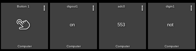
The main thing is it now parses the info returned by the board, and fills attributes. For instance, if digital input 1 changes, it fills the "digin1" attribute with "on" or "off". Same for adc values. By adding tiles to the dashboard using the "attribute" template, you can have that tile display any of these attributes from the MonaLisa. It'll look like this:
There's also 4 buttons defined so you can add a button 1 (or 2, 3, 4) to the dashboard to control each of the 4 digital outputs independently, and see the status of them using the digout1 (2, 3, 4) attribute(s). To add the button to the dashboard you select the "button" template, and enter the button number you want (1, 2, 3, 4).
I also exposed the "polladc0,1,4,5" and "nopolladc0,1,4,5" commands so you can tell the board to poll the adc0, 1, 4, or 5 or not. The adc polling is off by default when the board powers up (to prevent tons of messages if they're left floating - though in practice they seem pretty stable even when disconnected). The digital inputs are polled by default.
I know this is not really the "right" way to do these things. There is another driver available that makes child devices, which then expose the proper "capabilities". Personally I find that way more confusing, so I did it this way!
Catching this train a few years later, but finally decided to ride the coattails of @haas, @ogiewon, and @JohnRob.
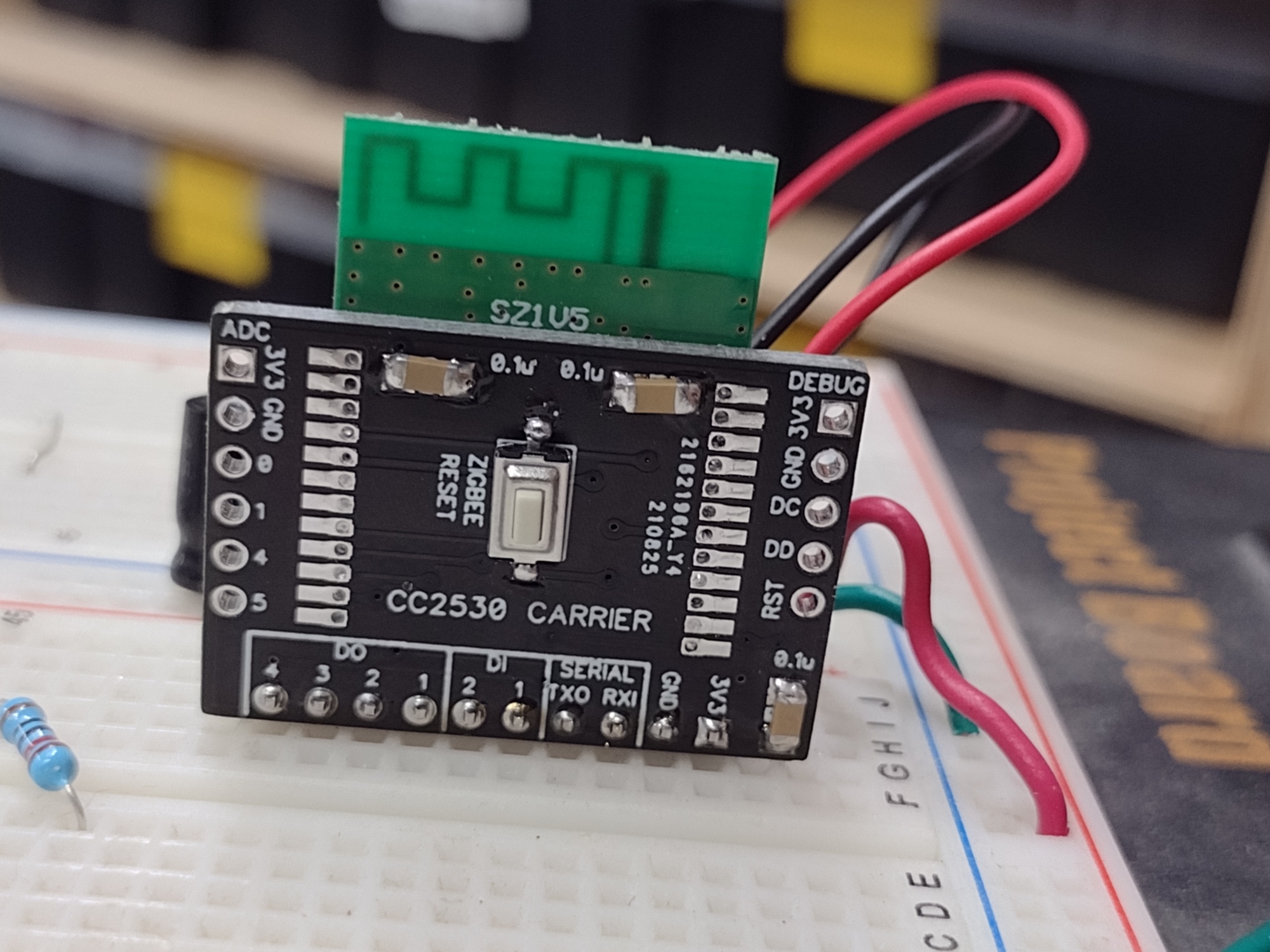
I am not even 100% sure how I will end up using this newfound power, but I wanted to have it as an available option. I chose to trim it to a minimalist carrier board that is friendly to both breadboard and stripboard (as a backplane).
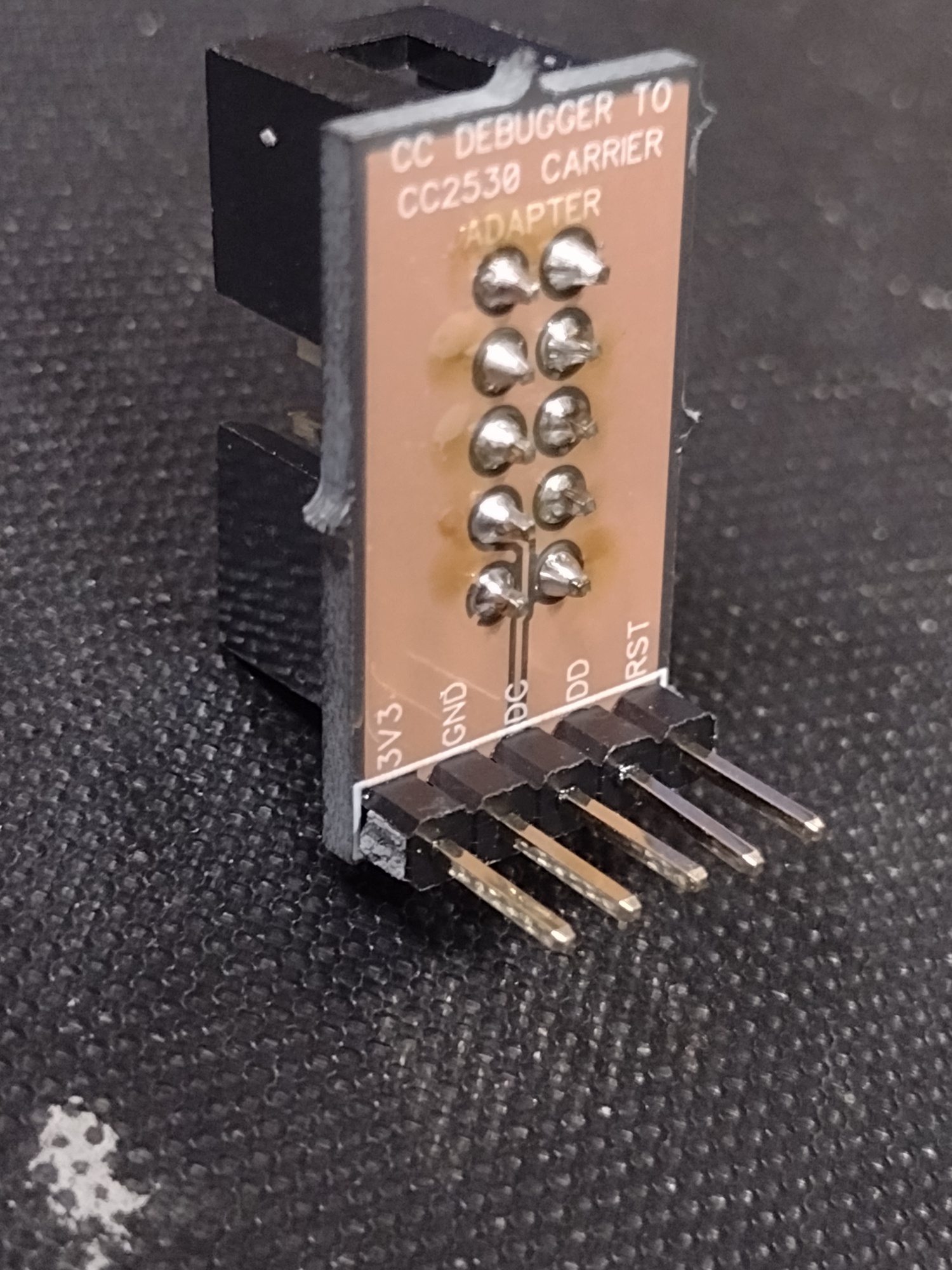
Add a CC Debugger tool ($9 on Aliexpress), and you are in business. I just loaded the firmware, installed the driver, and it added parent/child devices without a hitch. I sincerely appreciate everyone that provided the groundwork and inspiration!
Correct. The initial plan was to just use Dupont jumpers from the ribbon cable. Knowing the intended operator, it seemed prudent to make it more idiot resistant. So, I took advantage of the per-square-inch pricing at OSHpark to make a small adapter.
Curiously, have you ever tested any of the boards that have the range extender or PA chips? I picked up a couple of CC2530 + CC2592 modules, but wanted to test the known-good configuration first.
@haas Got a couple of these on the way and have read this thread plus the support doc. Just want to make sure I understand correctly...
You don't need an Arduino for the MonaLisa to interace with Hubitat. Using the driver from @ogiewon or your driver, MonaLisa can be added to HE as a Zigbee device, with whatever is attached to the GPIOs showing up as child devices - Is my understanding correct?
I have Arduino programming experience, but would prefer to just read and control the devices using rules in HE.
I have successfully added my MonaLisa to my Hubitat C7 and can control the outputs from the parent device. Thank You!
My use case is (initially) to send temperature data derived from 10 separate DS18B20 sensors connected to a Arduino MEGA over serial connection to the MonaLisa and then on to my Hubitat C7 where I can then display them on a dashboard. I have also equipped my MEGA to control 2 separate 8 channel relay boards which I will eventually want Hubitat to have control of.
What I do not understand is that the MonaLisa uses pins 2 & 3 for serial communication but the Arduino UNO & MEGA both use pins ) 0 & 1 for RX0 and TX0 respectively. On the MEGA I'd prefer NOT to use "serial 0" since that is the default for other uses. Should I just eliminate connections for pins 2&3 to the Arduino and hardwire the MonaLisa's serial connections from 2&3 to one the MEGA's other serial connections at 14 to 19?
Hi. The demo serial.ino script opens a second serial port on pins 2 3 on the Arduino. Then you can still use 0 1 for standard serial, typically back to a computer for serial debugging printouts.