Thingshield replacement for arduino over zigbee now available for hubitat

Glad the board is useful to you!

Yes, in the same github repository pointed to in the guide, there is a windows binary.


I haven't tried it, but it should work.

Yes, it is a repeater. Near the start of the guide: "It is a "router", meaning it is meant to be always powered on, and helps to route messages over the zigbee network."
You can verify the board's connections with the awesome lqireq. command.

Thank you for your response and work.
My issue wasn't CCLoader but this section of your explanation:
The
"objcopy --gap.............) I haven't been able to find "object.exe" to perform this step using a windows machine.

image

Oh. Note that the firmware is already provided in bin format. So you don't really need objcopy. But in case you somehow made your own hex file, you could use a windows bin to hex utility for windows like this..
http://hex2bin.sourceforge.net/

1 Like

Hi,

I have your MonaLisa running with Putty and I find it amazingly simple to use Kudos!

Question regarding the Groovy code.

In your "manual" you state that commands to the Mona Lisa should end with a period. However I can't see how that is happening in your groovy example. In my simple testing I see the code without a period is processed correctly but I'll guess adding the period is the correct way to send a command, even though it may work without.

Should I modify my groovy to add the period or is it indeed optional?

Thanks

John

Yes, commands should end in a period.
The line in the groovy code doing so is
mystr=mystr.padRight(16,".")

1 Like

Procedure to flash the MonaLisa cc2530 board using Windows and a NodeMCU V1.0 board.

(All the information below is the work of others before me. My only contribution is collecting it and applying it specifically to the Mona Lisa.)

While learning the MonaLisa board from Dr Haas I wanted to be able to flash the cc2530 board using a NodeMCU. My goal was driven by.

  1. I donā€™t own an Arduino UNO
  2. I feel much better flashing a 3.3V device with another 3.3V device. No 5V signals to be concerned about.
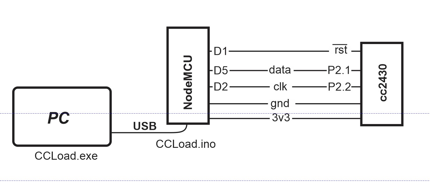
First letā€™s look at the process overall.

Simply stated the NodeMCU is programmed to be a simple programmer module. It will be used to program the MonaLisa with the firmware sent by the Windows computer running CCloader.exe.

There are three parts to the process.

  1. A windows computer (linux will use nearly the same steps) with two programs installed.
    a. Arduino IDE
    b. CCloader.exe

The computer will first use the Arduino IDE to load the CCloader.ino onto the NodeMCU board.
Then it will be used in a CMD window to run the CCloader.exe program

  1. The NodeMCU will receive data from the CCloader program and send the commands to the MonaLisa to flash the new code.

  2. The MonaLisa board: The program target.

CCloader.ino modification to use the NodeMCU

The original CCloader.ino code needs to be modified to enable the correct pins of the NodeMCU. In the Arduino editor replace the UNO pin numbers (around line 92) with:

// Debug control pins & the indicate LED
#define NodeMCU

#ifdef NodeMCU
// define pins for NodeMCU
   int DD = 14;
   int DC = 4;
   int RESET = 5;
   int LED = 2;
#else
// define pins for UNO
   int DD = 6;
   int DC = 5;
   int RESET = 4;
   int LED = 13;
#endif

Now program the NodeMCU with the modified CCloader.ino
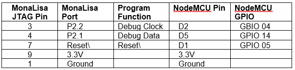
Connections:

Windows computer to NodeMCU: use a standard USB cable.

NodeMCU to MonaLisa:

MonaLisa
image


Flashing the MonaLisa:

Be sure to close the Arduino IDE else the port will be unavailable to CCloader.exe

With the Windows computer connected to the NodeMCU and the NodeMCU connected to the MonaLisa.

In one directory put the CCloader.exe and the MonaLisa firmware found in the original thread:
(BTW this is an awesome device !)

Create a text file with the following command line in it: (optional)

CCloader.exe <port#> <firmwarefilename.bin> 0

  • The port# is the same port# the Arduino used to communicate with the NodeMCU board.
  • For some reason I found it did not like me typing the firmwarefilename but worked when I copy and pasted the filename from windows explorer to the text file.
  • The 0 (zero) tells CCloader to expect a UNO (even though we have a NodeMCU)

From that directory open a CMD window:

  • Copy the command line from the text file to the CMD window (right click paste not Ctrl V)
  • Press enter.

You should see something like:

C:\work>CCloader.exe 7 SampleLight_v1.2_butt3reset_ieee_lqi.bin 0
Copyright (c) 2013 RedBearLab.com
CCloader.exe version 0.5
Comport : COM7
Bin file: SampleLight_v1.2_butt3reset_ieee_lqi.bin
Device  : Default (e.g. UNO)

Comport open!
<Baud:115200> <data:8> <parity:none> <stopbit:1> <DTR:off> <RTS:off>

File open!
Block total: 512

Enable transmission...
Request sent already!

plus many more lines of text as each block is uploaded.

Completed !

3 Likes

Update on my Haas Thingshield replacement.

I now have my first use of the MonaLisa board and firmware deployed and working. It monitors my alarm and reports to Hubitat. I had originally implemented this with Hubduino and it was working well, however I much prefer Zigbee over WiFi. Perhaps its a personality disorder of mine :slight_smile:

So again I thank Dr Haas for his creativity and willingness to share. And I hope knowing people are actually using his device brings him satisfaction.

1 Like

@JohnRob - Glad to hear MonaLisa is working well for you. Quick question - are you simply using the onboard GPIO of the MonaLisa, or are you augmenting it with an Arduino for additional GPIO pins?

My arduino (NodeMCU) "listens in" on the messages from the alarm to the keypads. They are simple ASCII phrases. I convert them to something < 15 char and use the MonaLisa passthru capability to send them to the Hubitat. This application does not use any of the cc2530 capabilities other than the Zigbee radio and serial input.

Philosophically I decided not to allow communication (aka control) to the alarm panel, only reading the messages. And with a little obfuscation even those are useless to anyone "listening in"

The arduino code handles slowing down the keypad messages which occur at a 10 second rate. And handles any error messages or warnings like AC LOSS.

1 Like

Very nice.
I used one myself the other day. I attached it to an arduino and have it able to wake up my computer (acting as a virtual keyboard that can send key presses/releases). Then if I'm not home, I can wake it up remotely, and then get in via Chrome remote desktop.

2 Likes

Is it possible with your firmware to put the cc2530 to sleep?

John

No. It is a "router" profile, which means it expects to always be awake and helps to route others' zigbee messages, just like the original ThingShield. It is not like meant for low power operations. It uses about 20mA, depending on what it's doing.

1 Like

PC Board design with protected I/O but without the "shield" connection functions.

I had such good luck with Dr Haas's board I decided to make a simple interface board. I stripped away the "shield" plugin capability and add some Input and output protection. This allowed me to drop the size to:

  • Carrier board only: 34 mm X 58 mm
  • Carrier board with cc2530 attached: 45 mm X 58 mm

I retained the LED's and the Zigbee repair button. But added:

  • Two of the analog inputs have places for input dividers, RF filters and a transient filter.
  • The other two only have dividers and RF filtering.
  • Digital inputs have simple RF filtering.

I purchased my boards from OSHPark and have built and tested one. The components are surface mount as I find them easier than through holes. I realize not everyone is as comfortable as I am soldering small devices. But I like to keep compact "tight" designs.

I have not yet authorized release of the design by OSHPark but will do so if anyone is interested. I will also put up a BOM and Schematic. Neither of these are too exciting.
I've already posted the process I made to update the firmware on the cc2530 board using a nodeMCU board. This makes the process much easier as both are 3.3V boards so there is no level shifting required.

JohnRob

1 Like

Do you think it's possible to run the hass bord on battery? Also do we have the size of the hass board? I need to make a The battery operated temperature sensor for the lake. I don't have power on the dock.

The Haas board is 28 mm x 20 mm. The Haas board is only the green board shown in the above post. The purple board is my design.

The Haas firmware is set to make the device a repeater as well as and Zigbee communication. It draws a nearly constant 20 ma. It will not make a good battery operated sensor.

Why not the Aqara Temp sensor? Amazon Link. They are cheaper if you buy them on eBay or Bangood etc.

@JohnRob
I need to be able to hook a DS18B20 prob to it.
The prob needs to sit in the lake.

1 Like

I don't know of any device that is battery operated and interfaces with a DS18B20. There used to be a contact sensor that would do this but they seem to be unavailable.

I know the Hubduino code with a nodeMCU board (WiFi) will interface with your sensor but it too is not meant for battery operation.

Perhaps a Solar panel and a local large battery?

DS18B20 can be connected with a long wire.

I personally run cat 5 wire of 10 feet with DS18D20. I also helped a member here who coincidently wire his DS18D20 to a lake. I think he run a longer wire than 10 feet. We are just using simple wiring.... nothing fancy.

I suspect that with CAT5 wire maybe a 100 feet wire should be do able. I have never tried it. At 100 feet, some care may have to be taken.

Here some documents on how to use DS18D20 with long wire. Guidelines for Reliable Long Line 1-Wire - Maxim Integrated

I hope it help if you are looking to wire solution.

Thanks for the info. I wish I could find one of these it would be perfect. https://www.climax.com.tw/new/tso-9-el-zb.php

Look at these #FGDW-002-1 to see if they will do what you want. They were hard to get but HD claims they have some.