Seriously useful automation and the kind of stuff that (to me) underlines how important it is to aim to build resilience and self recovery into the hub, "beyond hobbyist expectations".
While not "life support" nor "security" (as we are often warned about HE use thereof) I'm sure your daily operations would be hindered if this didn't function, or be recoverable-in-short-order once you have become reliant on it.
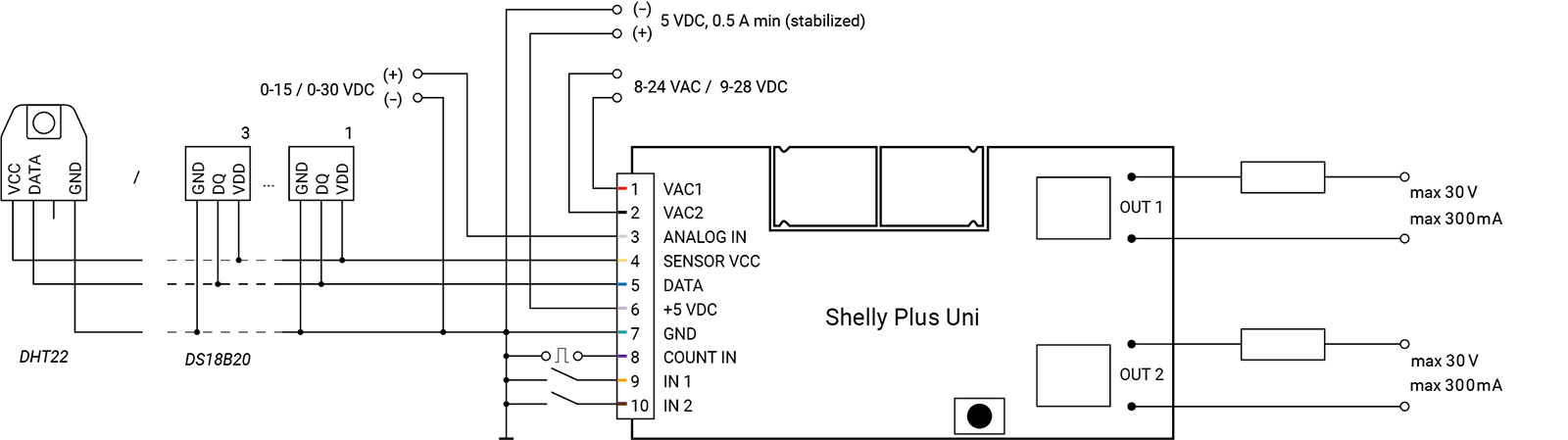
On the power side, just a note here that the Shelly Uni Plus can be powered directly from your furnace 24V AC supply. I'm running it off a 12V DC wall wart, but the power input specs are super flexible.
@PunchCardPgmr , I'm not sure how I feel about WIFI devices like Shelly, but it is a LOT more advanced than a typical zWave Zigbee device in that it can be programmed via the onboard web server with triggers, actions etc. almost like a mini hub. On getting it fired up, I was immediately struck with how a tiny device like this can be programmed pretty much all it's own to manage two dry contacts, or full power relays as many of their products. This particular part is only $22 CAD.
@velvetfoot , I have about a dozen temp sensors connected to Shelly Uni (as in yesterday), Fibaro's Smart Implant x 2, and four solar/battery powered sensors using the old Fibaro Door/Window sensor which can host a temp probe. They are all like these, typically a few dollars each.
The Fibaro Smart Implant has been rock solid connected to my HRV project. This is a good thing as I drive two PTC heaters (power is sent to these based on a continuous algorithm comparing fresh air exit temps vs the target temps) and two 6" AC Infinity ECM fans, with speeds being dialled in based on VOC, CO2 and Radon in the home. The relay in the Smart Implant is being used to put the HRV into defrost mode which again, needs to be rock solid at -35C to avoid unit freeze up.
The other Fibaro Smart Implant is the core of the pool solar heating system as the temp sensors (as well as a remote roof top solar powered sensor) manage the heating system for the pool very nicely.
The Shelly products offer a solution to do simple management of things like a pool pump on/off based on temp triggers, 100% without a hub if required, so again perhaps to some redundancy there.
Love Shelly, and glad to see that they are stepping into other technologies besides WIFI.
Other than 1 remaining device, I stopped using Shelly's and replace most of them with Z-Wave over the last 2 years. I wanted "less" dependency on WIFI for my devices. Have a box full of 1's, 2PM's, Dimmers, and RGBW.
Been giving them away to friends locally.
@jsprince , with WIFI, Shelly makes a battery powered sensor pretty tough to do (so they resort to Bluetooth it appears for battery powered sensors), but to be clear, the Shelly Uni Plus requires WIFI to program etc.
I am also more inclined to use Zigbee/zWave just for simplicity, but the Shelly bits have the advantage of being programmable for local triggers etc. which makes them pretty useful in the toolkit if you want some simple automation that is hub-less, offgrid, etc. I'm just a rookie with these devices so a lot to learn there.
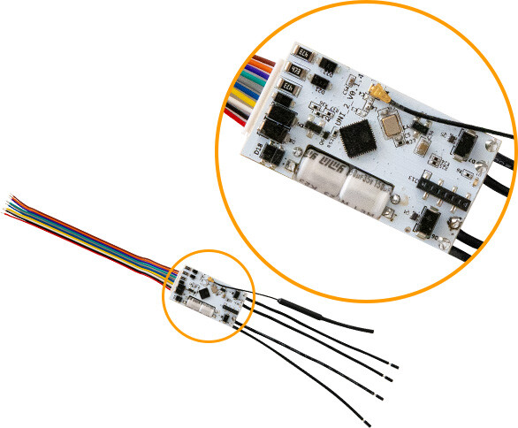
I updated the AC Infinity cover to include an out of the box module:
0-5V and 0-10V to 0%-100% V-PWM Module Board Voltage to PWM Signal Converter.
This along with a 2n2222 transistor, a 1K resistor and a 10k resistor allows you to control the AC Infinity with PWM instead of 0-10v. The 0-10v output of the Zen54 is converted to a 10v DC PWM Signal. Allows the fan to run at slower speeds, and a little quieter.
I’ve found the 0-10V effective as it does give me 99 “steps” of adjustment setting it up as a dimmer in Hubitat. How does this method vary from that? I’m not an expert in the world of PWM control by any means….
At some point I’ll have to start playing in the world of DIY 3D printing as well. I had an Alaris UV resin printer at my previous company but it was about $100K, insanely expensive to operate, and a PITA to maintain. The current crop of inexpensive 3D printers are literally 1/100 the cost.
While the 0-10V control method generally functions as expected, the pulse is based on a constant 10V, with the pulse width determining the "on time." After testing approximately 30 fans using only 0-10V control, I found that at lower speed settings—30% or below—torque begins to drop, and the fans appeared to be noisier. Depending on the fan, starting at 20% or lower may prevent the fan from spinning at all. However, by maintaining the 10V and adjusting the pulse width as designed, most fans achieved nearly full speed range.
I think either works fine. In my case, I wanted to have "lower speeds" available 24x7 with the ability to ramp up when needed.
Has anyone tried this with the vevor fans? The pricepoint is pretty compelling compared to AC Infinity fans. I've got one on order, just curious if anyone else has already figured it out.
I have not, but based on prior experience with AC Infinity, Fantech and Terrabloom the Vevor fans will likely be the same. Post up pics when you get it please.
With respect to pulse width vs 0-10V with the AC infinity fans, and Terrabloom, I definitely run them as low as 5 (of 99 steps) every hour for HRV condensate draining, and they do run at very slow speeds, pretty much silent. It's been two years now. I will say that when I had them connected incorrectly (grey to AC Infinity white-tach instead of grey to AC Infinity black - ground) they did not run well at low speeds at all. It's interesting that they ran at all connected like that, but they did. Once fixing that wiring, they work exactly as I would expect right down to 5% (pretty much off). In my system with duct mufflers etc. the fans all become pretty much silent below 40% or so.
Ok, got everything today and started playing with it and haven't quite got it working just yet so maybe someone will have ideas.
Fan: VEVOR Inline Duct Fan, 8-Inch 807 CFM with Temperature Humidity Controller, Quiet EC-motor Ventilation Exhaust Fan for Cooling Booster, Grow Tents, Hydroponics
Wiring:
Line Input
Black (Line), White (Neutral), Green (Ground)
Controller
Black (-), Red (+), Yellow (M)
Motor
Blue (M), Black (-), Red (+)
With the controller connected, measured DC voltage from Motor Blue -> Motor Black:
1: 1.38V
2: 1.66V
3: 2.07V
4: 2.39V
5: 2.71V
6: 3.03V
7: 3.38V
8: 3.70V
9: 4.25V
10: 4.90V
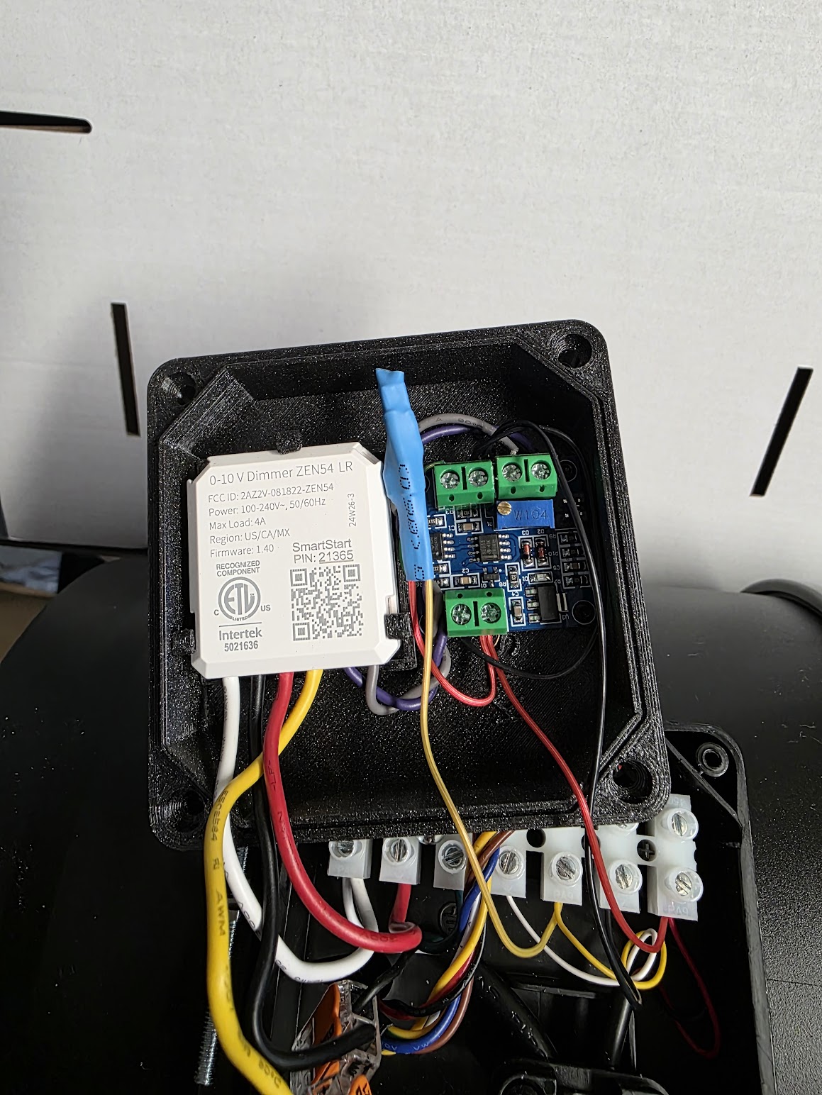
With that I connected the Zen54 as follows:
Zen54-Line -> Line Black
Zen54-Neutral -> Line Neutral
Zen54-Load -> Not Used
Zen54-SW -> Not Used
Zen54-0-10V -> Motor Blue (M)
Zen54-Gnd -> Motor Black (-)
I set the Zen54 parameters for minimum brightness = 13 and maximum brightness = 55 to stay within the voltage range that I measured.
Turning on the Zen54 to any level it seems I'm getting the expected Voltage output on Motor Blue (M) but the fan doesn't turn on until I hit 40% and then it's on at full blast and going lower = fan off and higher doesn't seen to change any speed at all.
Red to the motor is ~24V (23.58V with fan on full speed, 23.69V with fan off) with the external controller disconnected. It is the same with the controller connected.
The potentiometer would be set to 20kHz, and then the device should be able to take the Zen54 0-10V analog control to 5V 20 kHz PWM connected to the Vevor fan. Looks like jumpers to set 0-10V or 0-5V input and 5V or 24V PWM output, with a potentiometer that would need to be dialed up to 20kHz.
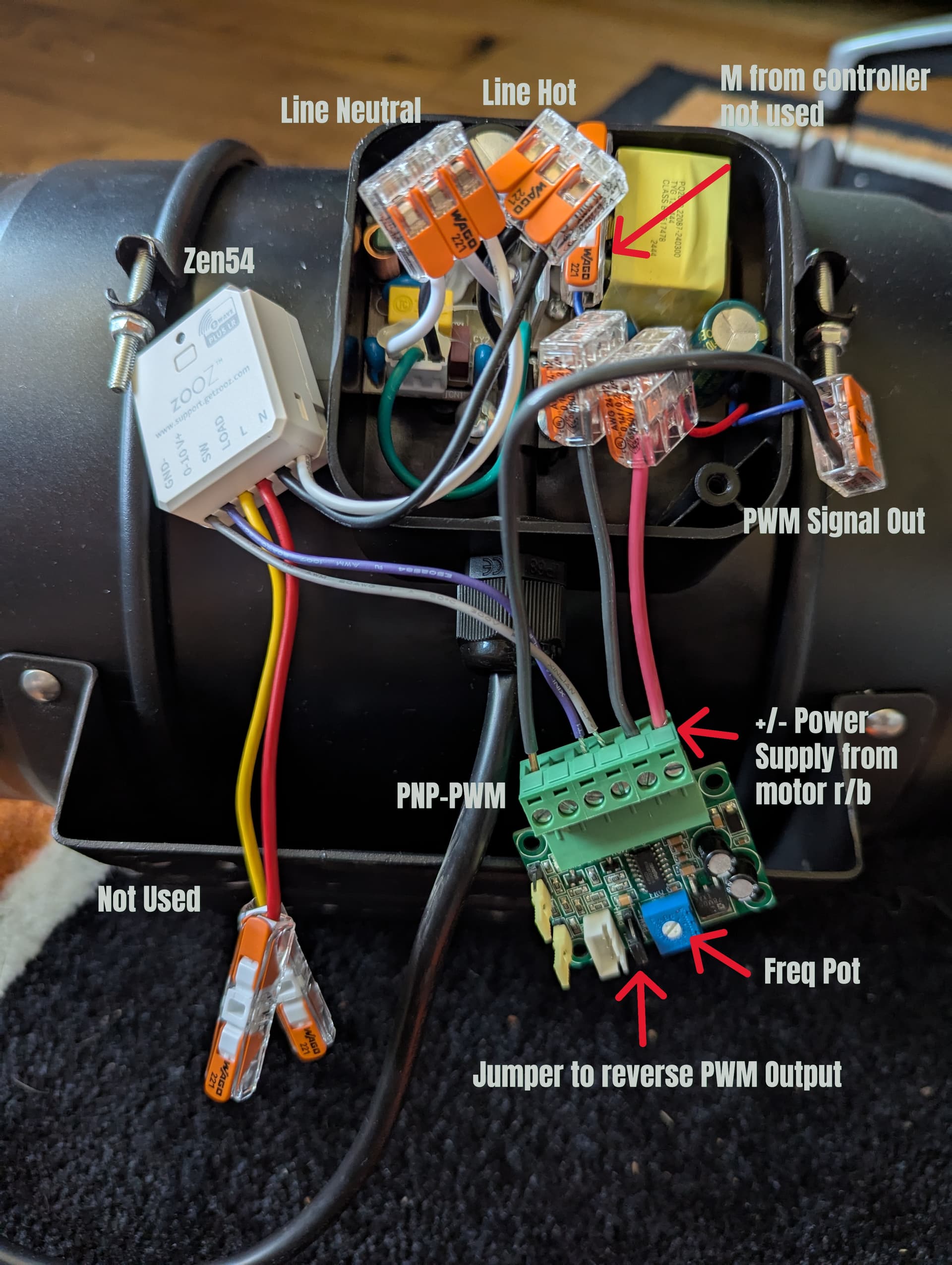
Thanks for the recommendation! There are tons of the same board on Amazon from different sellers so ended up getting one for $12. I was able to hook it up this morning and it worked like a charm. So all in all it's still a pretty good savings from the other brands considering the 8" fan was $77 + $12 PWM converter = ~$90 compared to the cheapest AC Infinity fan at $139.
There's a jumper next to the potentiometer that has to be reversed, if you don't then 100% brightness outputs ~0V (had me confused for a bit).
Use the PNP-PWM (sources voltage) output on the board to output 0-5V.
I completely removed the supplied controller cable to make more room in the housing - it was hot glued in so just took a little effort to remove the connector.
I'll probably 3d print a cover like others have for the infinity fans and clean up all the wiring but the picture with it spread out makes it a little easier to understand.
Awesome and thanks for taking the time to post up your solution with a nicely labeled pic for others who may take the same path :-). This thread may very well be the goto for folks doing automation with these EC fans