Would you mind posting how you setup tasmota sync and tasmota to control your servos?
I'm glad you were able to answer your own question. Multiple "dimmers" on the same device would be a very unusual configuration, but there is a single dimmer device that also has the Custom Command option that might be cleaner than using the Sensor option. Just a thought.
1 Like
I have come up with a solution which works for my use case. I open my blinds to a set position consistently so if you do the same this may work for you. I followed the Tasmmota doc for a dual servo setup on one esp mcu (i have a mixture of single and dual servo setups)
I found this rule while perusing tasmota docs. and have adopted it for my dual servo use case. '50' is the position of the blind. (range is 0-100)
Rule on power3#state=1 do backlog ShutterPosition1 50; ShutterPosition2 50 ENDON on power3#state=0 do backlog ShutterPosition1 0; ShutterPosition2 0 ENDON
To use, remove all rules from your Tasmota blind mcu.
- In tasmota console remove all existing rules, rule1 ", rule2 ", rule3 ", etc.
- Remove the Tasmota sync device for your blinds
- install the above rule and activate it.
- test it by going to the tasmota web console for your blind mcu and toggle relay3 (both blinds should open/close
- Install the tasmota sync quad relay driver and configure as normal.
Switch 3 will open/close both blinds with on/off.
Its a kludge buts works.
1 Like
I created two pwm channels in tasmota configuration. I had to activate multiple servo by the console in tasmota. I can't recall the exact function number. This step was important so one dimmer (pwm channel) didn't affect the other one. This wasn't clearly defined online and wasted much time of mine.
Then setup a tasmota dimmer in hubitat.then issued custom commands under rule machine. Two strings. One Channel# where # is the channel number as in the number assigned to that pwm channel. The other string is a number between 1 and 99.
I can look over it and provide more detail and screenshots if you like. I'm away from it as I type this.
Edit: When I had two pwm I found one affected the other one. Typing "setoption68 1" into the console unties them and they both operate independently.
Thanks @kuzenkohome . I looked at using the shutter mode. Which I believe you are using. I'll keep what you have done in mind.
At the moment I'll stick with using the dimmer and custom commands as I set my blinds to three states, closed, fully open, and privacy which is mostly dipped.
On my front blinds (also Venetians, in the living space only) I chase the sun in the morning, as in adjust them based on where the sun is in the sky to let the most light in. Currently doing that with hubduino but I may look into changing those over to tasmota.. But they still work so I don't see myself doing that in a hurry.
Stick with what works for you. I also used (and still use) Hubduino when I started with Hubitat 4 years ago, but ran into performance issues (C4 model with OS memory leak and no fix, upset at that), had to reboot every week.
Also had some zigbee devices that were not supported by Hubitat (my mistake in purchasing) so I had found Zigbee2MQTT/Node-Red/Tasmota and have moved a lot of my stuff over and like it for the open source nature.
But I still use hubitat due to the strong community support. May purchase a C8 eventually.
Everytime I use the refresh-Method new values are fetched... ![]()
But after some seconds this error is raised: ![]()
Failed to find child C0A8B252-ep1 - exception null
What's going on?
I’m traveling at the moment and won’t be back until the end of the month so I can’t go into any detail.
What that error is saying though is that it is trying to contact child devices but they don’t exist.
Could be a code error or it could be that your device driver is configured to expect child devices, but they don’t exist.
Are you configured for\expecting child devices.
1 Like
It'a simple power switch - so I expect no child device. ![]()
Have a look in the State variables for “useChildDevices”. It should be false in your case. If it shows as true then click on ChildrenRemove and try it again.
useChildDevices shows false.
BTW: There is no ChildrenRemove-Button.
What I also noticed:
- It shows needlessly
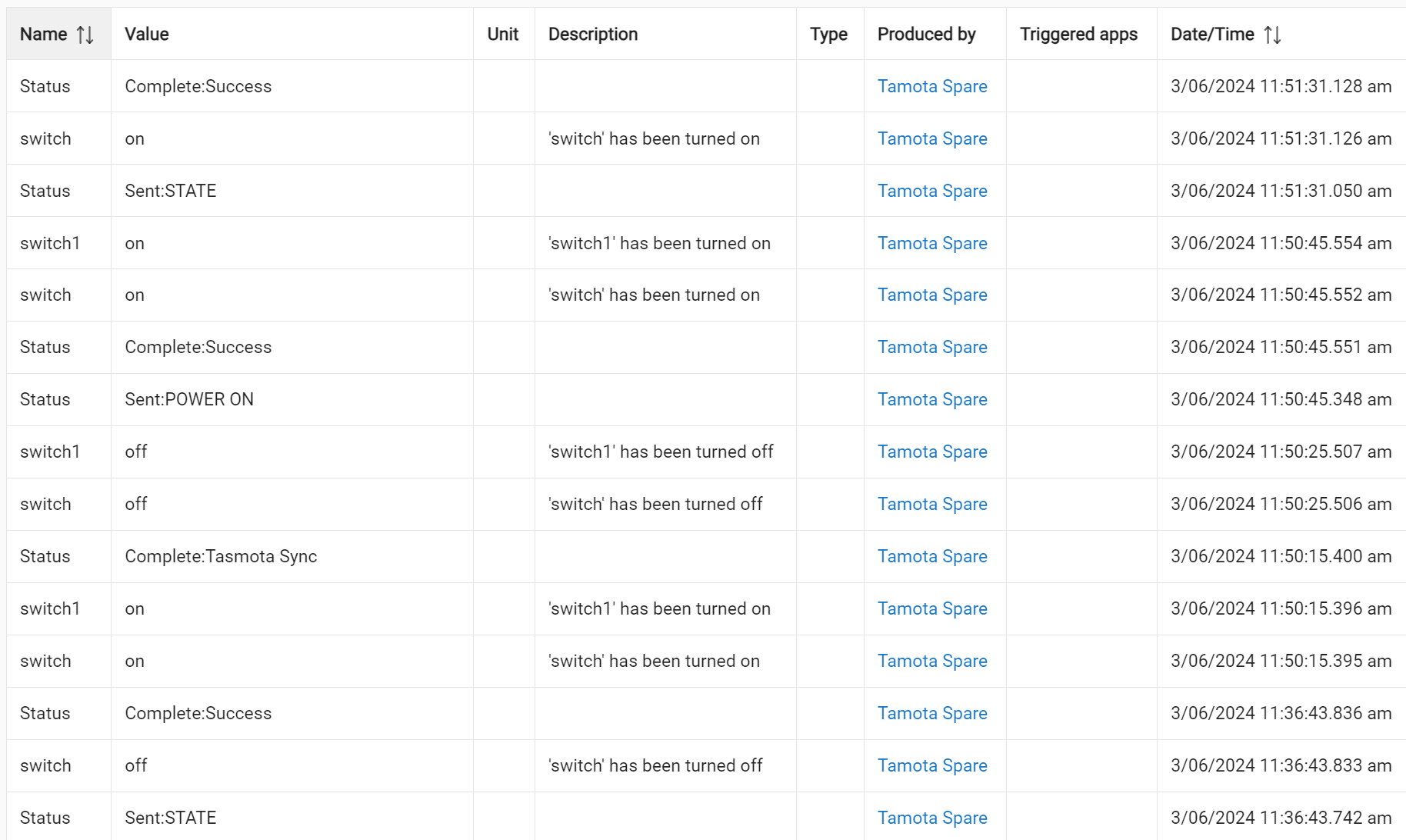
switchandswitch1states. - The events for
switch1are much more reliable than usingswitch(e.g. which doesn't fires when I turn on/off the switch manually). - Turning the switch off doesn't reset the power value.
switchfires "on", even when it is already "on" -switch1correctly only fires once.
It would be great to have a simple device driver (without any childs, just a single power switch). ![]()
I'm home again and happy to work with you on this.
I just took a simple Sonoff S31.
Installed the current version of Tasmota (13.4.0.2).
Added it to Hubitat using the current Tasmota Sync driver version V1.3.4

Note: This driver does not use any Child Devices. Those only appear as an option with the dual\quad\octo options.
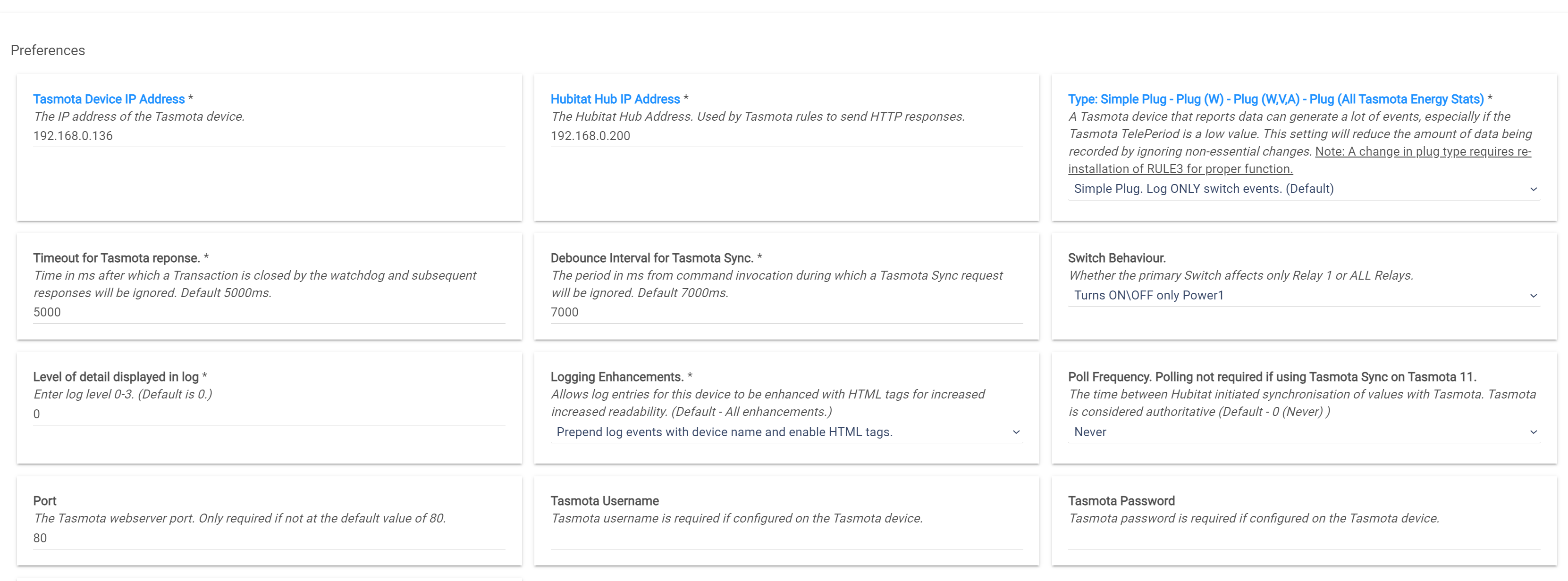
Left all the settings at default values except device and Hub IP's.
Did an Initialize.
Did Tasmota Inject Rule.
Everything works as expected whether I'm switching things off\on from Hubitat or from Tasmota. Where you might run into trouble is if on\off happens in quick succession. Responses may be ignored if they fall within the Debounce Interval and will always be ignored if they fall outside the Timeout for Tasmota response.
The reason that there exists both a switch and switch1 is simply to do with naming. In a single relay just using switch makes the most sense. However, in a 8 relay device using switch1 - switch8 makes the most sense. I opted to use the switch1 - switch8 naming, but also having "switch" always follow the state of switch1 regardless of how many relays there were. This way I can have a single driver for any number of relays 1-8 and just change a couple of parameters instead of maintaining a completely separate driver.
In a single relay you will have switch and switch1, which should always be the same and you should be able to use either one for rules etc.
In my testing of a single relay the value of switch and switch1 are in lock step regardless of where I turn it on\off from.
What I do notice though, is that when I do a refresh (Sent: STATE) it is saying that the value of "switch" has been turned on or off, even when it is already in that state.
Is this what you are referring to with this comment?
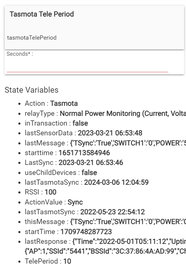
Tasmota only transmits the power information at the Teleperiod interval and the lowest this can be set it 10 seconds (default 300). When you turn on a device with a load the values will only update after the TelePeriod. Likewise, when the switch is turned off the stats will only go back to 0 at the next TelePeriod interval. I think this is what you are seeing. You can use the interface to set it to a lower TelePeriod. You can also use a rule to shorten the TelePeriod when the switch is in the On state to shorten the TelePeriod and revert to a longer TelePeriod when the switch is off. This will result in a lower load on the Hub.
Yes!
I wondered why my rules are fired more than once...
BTW, using switch and not switch1 has a big advantage:
E.g. in a Rule Machine condition you can use the device as simple Switch; But using switch1 forces you to get the state as Custom Attribute - much more complicated.
Therefore it's a pity that switch is not reliable.
In such situations I'm simply using a rule to just fire a refresh. ![]()
But it would be much better when the driver itself would set the power value to 0 when the button is turned off, and do a refresh when the button is turned on.
With the current driver the "refresh by rule" is needed for every device...
Just want you to know this is on my list. I have an update for TIle Builder I'm working on and once I get that done I'll take a look at this.
1 Like
Before I publish any code try making these two changes. It should correct the issue of getting a state change reported when doing a refresh.

I understand what you are asking. I feel like I already tried that back when I was writing the driver and decided not to do it for some reason I no longer remember. I'll take a look but no promises.
1 Like
OK, I've set isStateChange to false...
Yesssss, this works! ![]()
Of course the big question is:
Why didn't you originally leave the value at the default (which is false)? ![]()
I just added this code in line 1698 - and this seems also to work: ![]()
if (status == 'on')
  runIn 1, 'refresh'
else
  sendEvent name: "power", value: 0, descriptionText: "'power' has been reset"
Sounds like a cop-out but I actually didn't write that part. Someone else added the child behaviour to my original driver. It's possible that I changed it, but not going to spend the effort to find out.
Your code was pretty good but I tweaked it a little to make sure non-existent attributes don't get set to 0 and then show up on the attribute list.
I'm afraid this is no good because it causes a loop. It's calls refresh, which retrieves state, which in turn calls this which makes sure that on/off state is mirrored in the device driver.
if (status == 'on') runIn 1, 'refresh'
I'll give it a closer look.
1 Like
Fin
Final code for this section looks like this:
    //Going from off to on. Force the Power stats to refresh after a change in state from off to on.
    if ( status == 'on' && device.currentValue("switch") == 'off' &&  device.currentValue("switch1") == 'off' ) {
            def parameters = ["STATUS","8"]
            //Don't run the command until after the debounce window has closed or it will be ignored.
            runInMillis(settings.debounce - remainingTime() + 100, "callTasmota", [data:parameters])
    }

    //Going from on to off. Set the power stats to 0. What gets reset depends on the User selected power monitoring level.
    if ( status == 'off' && device.currentValue("switch") == 'on' &&  device.currentValue("switch1") == 'on' ) {
        if (settings.relayType.toInteger() >= 1 ) sendEvent name: "power", value: 0, descriptionText: "'power' has been reset"
        if (settings.relayType.toInteger() >= 2 ) sendEvent name: "current", value: 0, descriptionText: "'current' has been reset"
        if (settings.relayType.toInteger() >= 3 ) {
            sendEvent name: "apparentPower", value: 0, descriptionText: "'apparentPower' has been reset"
            sendEvent name: "powerFactor", value: 0, descriptionText: "'powerFactor' has been reset"
            sendEvent name: "reactivePower", value: 0, descriptionText: "'reactivePower' has been reset"
            }
        }
Version 1.3.5 of Tasmota Sync for Relays has been published.
Fixes a bug in how switch\switch1 report state that resulted in excess reporting of state change.
Improves the speed at which power stats are initially updated after a change in switch state.
This applies to the Single, Dual, Triple, Quad and Eight_Relay_Switch_Plug drivers.
2 Likes
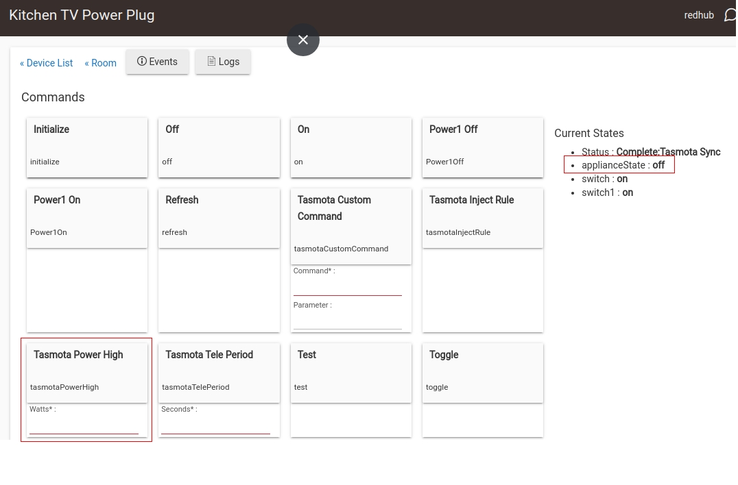
Thanks for this native driver, it made adding Tasmota devices (that I accidentally bought from AliExpress) to a Hubitat environment a breeze. So much so that I bought some more because it allows more device side control in the form of TelePeriod being configurable to suit the application.
I have added code for "applianceState" [On/Off] based on the PowerHigh threshold to add basic On/Off state to old dumb devices like my TV.
I tried add a diff in the reply against 1.3.5 as a tribute to your code, but it did not work. Can send it to you if you think that it would be useful.
Regards,
Dan
1 Like