I am trying to re-incarnate my Hubduino RFID Reader project based on RC522 chip.
The entire updated project will have:
- one contact sensor (door open/close status);
- two relays (control for OpenSesami door operator);
- RGB LED Stip (status on what is going on);
- RFID Reader (door access with RFID Tags);
New (updated) project is created step-by-step.
In a past I already created working and debugged Hubduino (Arduino) RFID Reader Sketch.
This should not be a problem to add it to a new project.
The target board is ESP-WRCOM-32 module.
Sketch (there is no RFID portion yet) compiles without any warning/errors.
All Child Devices created on the HE side and seems to be functional.
Sensor and Relay related portion is working just fine.
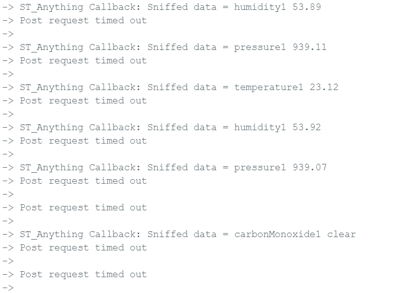
But I cannot make RGB LED portion working.
Output pins, defined for the controlling RGB channels (default are A0, A3, A6) on a scope
looks floating. By default these are Analog IO Pins. Somewhere they must be re-defined as
a Digital Outputs but I cannot find a correct place were is is done.
@ogiewon could you please advice what I am missing.
Just in case here is a Sketch in a current state (no RFID Code yet):
//******************************************************************************************
// File: ST_Anything_Relays_ESP8266.ino
// Authors: Dan G Ogorchock & Daniel J Ogorchock (Father and Son)
//
// Summary: This Arduino Sketch, along with the ST_Anything library and the revised SmartThings
// library, demonstrates the ability of one NodeMCU ESP8266 to
// implement a multi input/output custom device for integration into SmartThings.
//
// The ST_Anything library takes care of all of the work to schedule device updates
// as well as all communications with the NodeMCU ESP8266’s WiFi.
//
// ST_Anything_Relays_ESP8266 implements the following ST Capabilities as a demo of what is possible with a single NodeMCU ESP8266
// - 3 x Relay Switch devices
//
//
// Change History:
//
// Date Who What
// ---- --- ----
// 2015-01-03 Dan & Daniel Original Creation
// 2017-02-12 Dan Ogorchock Revised to use the new SMartThings v2.0 library
// 2017-04-17 Dan Ogorchock New example showing use of Multiple device of same ST Capability
// used with new Parent/Child Device Handlers (i.e. Composite DH)
// 2017-05-25 Dan Ogorchock Revised example sketch, taking into account limitations of NodeMCU GPIO pins
// 2017-11-27 Kai Lenk Modified to 3 relaySwitch
// 2017-11-29 Dan Ogorchock Revisions to make sure works for Kai Lenk
// 2018-02-09 Dan Ogorchock Added support for Hubitat Elevation Hub
//
//******************************************************************************************
//******************************************************************************************
// SmartThings Library for ESP32WiFi
//******************************************************************************************
#include <SmartThingsESP32WiFi.h>
//******************************************************************************************
// ST_Anything Library
//******************************************************************************************
#include <Constants.h> //Constants.h is designed to be modified by the end user to adjust behavior of the ST_Anything library
#include <Device.h> //Generic Device Class, inherited by Sensor and Executor classes
#include <Sensor.h> //Generic Sensor Class, typically provides data to ST Cloud (e.g. Temperature, Motion, etc…)
#include <Executor.h> //Generic Executor Class, typically receives data from ST Cloud (e.g. Switch)
#include <InterruptSensor.h> //Generic Interrupt "Sensor" Class, waits for change of state on digital input
#include <PollingSensor.h> //Generic Polling "Sensor" Class, polls Arduino pins periodically
#include <Everything.h> //Master Brain of ST_Anything library that ties everything together and performs ST Shield communications
#include <IS_Contact.h> //Implements an Interrupt Sensor (IS) to monitor the status of a digital input pin
#include <EX_Switch.h> //Implements an Executor (EX) via a digital output to a relay
#include <EX_RGB_Dim.h> //Implements an Executor (EX) for a RGB LED or strip with PWM using 3 digital output pins
//*************************************************************************************************
// WiFi Credentials
#include "credentials.h"
//*************************************************************************************************
//NodeMCU v1.0 ESP8266-12e Pin Definitions (makes it much easier as these match the board markings)
//*************************************************************************************************
//#define LED_BUILTIN 16
//#define BUILTIN_LED 16
//
//#define D0 16 //no internal pullup resistor
//#define D1 5
//#define D2 4
//#define D3 0 //must not be pulled low during power on/reset, toggles value during boot
//#define D4 2 //must not be pulled low during power on/reset, toggles value during boot
//#define D5 14
//#define D6 12
//#define D7 13
//#define D8 15 //must not be pulled high during power on/reset
// ESP32 WDOOM IO Pins
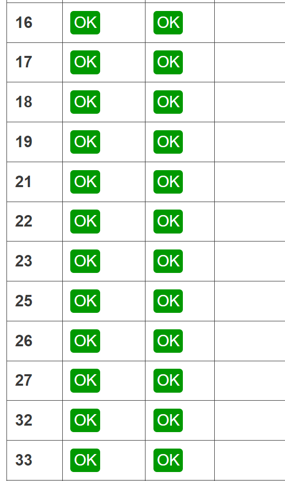
#define IN1 14
#define OUT1 25
#define OUT2 26
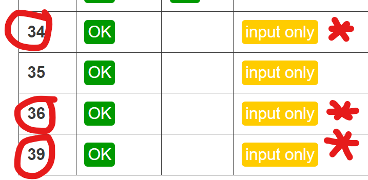
#define PIN_RGB1_Red A0 //(GPIO 36) SmartThings Capability "Color Control"
#define PIN_RGB1_Green A3 //(GPIO 39) SmartThings Capability "Color Control"
#define PIN_RGB1_Blue A6 //(GPIO 34) SmartThings Capability "Color Control"
//******************************************************************************************
//Define which Arduino Pins will be used for each device
//******************************************************************************************
#define PIN_CONTACT_1 IN1 //Hubitat Capabilities - DIO Pin (Normally Open!)
#define PIN_RELAY_1 OUT1 //SmartThings Capability "Relay Switch"
#define PIN_RELAY_2 OUT2 //SmartThings Capability "Relay Switch"
//******************************************************************************************
//ESP832 WiFi Information
//******************************************************************************************
// Set your WiFi details so the board can connect to the WiFi and Internet
// Get Credentials from the credentials.h file
const char* str_ssid = mySSID;
const char* str_password = myPASSWORD;
IPAddress ip (192, 168, 20, 151); // Device IP Address // <---You must edit this line!
IPAddress gateway (192, 168, 20, 1); // Router Gateway // <---You must edit this line!
IPAddress subnet (255, 255, 255, 0); // LAN Subnet Mask // <---You must edit this line!
IPAddress dnsserver (192, 168, 20, 1); // DNS Server // <---You must edit this line!
const unsigned int serverPort = 8090; // Port to run the HTTP Server on
// Hubitat Hub TCP/IP Address
IPAddress hubIp (192, 168, 20, 90); // Hubitat Hub IP // <---You must edit this line!
// Hubitat Hub TCP/IP Address
const unsigned int hubPort = 39501; // Hubitat Nub Port
//******************************************************************************************
//st::Everything::callOnMsgSend() optional callback routine. This is a sniffer to monitor
// data being sent to ST. This allows a user to act on data changes locally within the
// Arduino sktech.
//******************************************************************************************
void callback(const String &msg)
{
// Serial.print(F("ST_Anything Callback: Sniffed data = "));
// Serial.println(msg);
//TODO: Add local logic here to take action when a device's value/state is changed
//Masquerade as the ThingShield to send data to the Arduino, as if from the ST Cloud (uncomment and edit following line)
//st::receiveSmartString("Put your command here!"); //use same strings that the Device Handler would send
}
//******************************************************************************************
//Arduino Setup() routine
//******************************************************************************************
void setup()
{
//******************************************************************************************
//Declare each Device that is attached to the Arduino
// Notes: - For each device, there is typically a corresponding "tile" defined in your
// SmartThings Device Hanlder Groovy code, except when using new COMPOSITE Device Handler
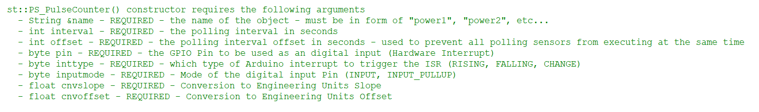
// - For details on each device's constructor arguments below, please refer to the
// corresponding header (.h) and program (.cpp) files.
// - The name assigned to each device (1st argument below) must match the Groovy
// Device Handler names. (Note: "temphumid" below is the exception to this rule
// as the DHT sensors produce both "temperature" and "humidity". Data from that
// particular sensor is sent to the ST Hub in two separate updates, one for
// "temperature" and one for "humidity")
// - The new Composite Device Handler is comprised of a Parent DH and various Child
// DH's. The names used below MUST not be changed for the Automatic Creation of
// child devices to work properly. Simply increment the number by +1 for each duplicate
// device (e.g. contact1, contact2, contact3, etc...) You can rename the Child Devices
// to match your specific use case in the ST Phone Application.
//******************************************************************************************
//Polling Sensors
//Interrupt Sensors
// Name, IO Pin, Initial State, Internal Pullup, Number of Loop Counts
static st::IS_Contact sensor1(F("contact1"), PIN_CONTACT_1, LOW, false, 500);
//EX_Switch arguments(Name, Pin, Initial State, Invert Logic) change last 2 args as needed for your application
static st::EX_Switch executor1(F("switch1"), PIN_RELAY_1, HIGH, true);
static st::EX_Switch executor2(F("switch2"), PIN_RELAY_2, HIGH, true);
// RGB Dimmer
static st::EX_RGB_Dim executor3(F("rgbSwitch1"), PIN_RGB1_Red, PIN_RGB1_Green, PIN_RGB1_Blue, true, 0, 1, 2); // channels (0,1,2) must be unique per ESP32
//*****************************************************************************
// Configure debug print output from each main class
// -Note: Set these to "false" if using Hardware Serial on pins 0 & 1
// to prevent communication conflicts with the ST Shield communications
//*****************************************************************************
st::Everything::debug = true;
st::Executor::debug = true;
st::Device::debug = true;
st::PollingSensor::debug = true;
st::InterruptSensor::debug = true;
//*****************************************************************************
//Initialize the "Everything" Class
//*****************************************************************************
//Initialize the optional local callback routine (safe to comment out if not desired)
st::Everything::callOnMsgSend = callback;
//Create the SmartThings ESP32WiFi Communications Object
//STATIC IP Assignment - Recommended
st::Everything::SmartThing = new st::SmartThingsESP32WiFi(str_ssid, str_password, ip, gateway, subnet, dnsserver, serverPort, hubIp, hubPort, st::receiveSmartString);
//DHCP IP Assigment - Must set your router's DHCP server to provice a static IP address for this device's MAC address
//st::Everything::SmartThing = new st::SmartThingsESP8266WiFi(str_ssid, str_password, serverPort, hubIp, hubPort, st::receiveSmartString);
//Run the Everything class' init() routine which establishes WiFi communications with SmartThings Hub
st::Everything::init();
//*****************************************************************************
//Add each sensor to the "Everything" Class
//*****************************************************************************
st::Everything::addSensor(&sensor1);
//*****************************************************************************
//Add each executor to the "Everything" Class
//*****************************************************************************
st::Everything::addExecutor(&executor1);
st::Everything::addExecutor(&executor2);
st::Everything::addExecutor(&executor3);
//*****************************************************************************
//Initialize each of the devices which were added to the Everything Class
//*****************************************************************************
st::Everything::initDevices();
}
//******************************************************************************************
//Arduino Loop() routine
//******************************************************************************************
void loop()
{
//*****************************************************************************
//Execute the Everything run method which takes care of "Everything"
//*****************************************************************************
st::Everything::run();
}