It appears you may have missed the second half of my post above? ![]()
Sorry, I did miss the second part of your response (need to stop reading on the phone!).
When I had the sensor working with Domoticz, I found that the operating range was rather narrow - about 400 or so. The map I used successfully was: map(soil_hum, 3500, 3100, 50, 80). The number was lower when it was wetter, so I had the input values reversed. The Arduino map function specifies that the values can be reversed to support reverse mapping so I didn't think it would be a problem, since it worked with my Domoticz sketch.
I ran some tests with the Hubduino code today to get an updated set of ADC readings using the following line:
static st::PS_Voltage sensor5(F("voltage1"), 10, 1, PIN_VOLTAGE_1);
Since I can't specify the desired number of samples without including mapping parameters, I expected the readings to be a bit off from what I had expected. However they still illustrate the narrow range as follows:
When the sensor is placed in a sealed bag with desciant, I get this:
Average: 3524 for 44% humidity - Min: 3406 Max: 3577
When immersed in water, I get this:
Average 3207 Min: 3079 Max: 3333
So, this tells me that the range when running in this sketch is 3079 - 3577.
I modified the HubDuino sketch to use this line;
static st::PS_Voltage sensor5(F("voltage1"), 10, 1, PIN_VOLTAGE_1, 3079, 3577, 0, 100);
... and get this result
20:13:07.945 -> Everything: Sending: voltage1 -475.70
When reversing the map values so that wetter is lower:
static st::PS_Voltage sensor5(F("voltage1"), 10, 1, PIN_VOLTAGE_1, 3577, 3079, 0, 100);
... I get this result
20:19:21.446 -> Everything: Sending: voltage1 576.31
I have a pretty good understanding of how to use the map function Arduino script but can't seem to get this to work correctly with PS_Voltage.
Art
Thanks for the detailed feedback. I will take a look at this and set up a system to test it. It may take a day or two before I can find some free time.
Thanks, Dan. I appreciate you taking the time to look into this.
Let me know if there is anything you would like me to try.
Meanwhile, I'll work on enabling the battery voltage monitoring channel to see how that works out. My suspicions are that it may produce desired results because the ADC values will be much lower than the soil moisture sensor.
Okay, it is all coming back to me now. It's been ~5 years since I wrote that code! ![]()
In order to use the PS_Voltage device with an ESP32, you need to be aware of a few things.
First, is this section of code in the ST_Anything_Multiples_ESP32WiFi.ino sketch. This code determines how many bits the ESP32's ADC will use. Thus, this determines the maximum integer value that will be returned from the analogRead() command.
Buried in the comment section below, you will find the proper min/max ranges based on the number of bits chosen. In my example sketch, 11 bits are used and thus the min/max is 0/2047. Based on what you've shared previously, it sounds like you should change the 11 to 12 bits as shown below, which will yield a min/max of 0/4095.
  //******************************************************************************************
  // Setup the default values for the ADC.  Used for analog voltage reads.
  //  Notes:  analogReadResolution(12) sets the resolution for all pins. 12 = 0-4095, 11 = 0-2047, 10 = 0-1024, 9 = 0-512
  //          analogSetAttenuation(ADC_11db) sets the attenuation for all pins.  11db = 0-3.3v, 6dB range = 0-2.2v, 2.5db = 0-1.5v, 0db = 0-1v
  //          analogSetPinAttenuation(A7, ADC_11db) sets the attenuation for individual pins.
  //******************************************************************************************

  analogReadResolution(12);        // Default of 12 is not very linear.  Recommended to use 10 or 11 depending on needed resolution.
  analogSetAttenuation(ADC_6db);   // Default is 11db which is very noisy.  Recommended to use 2.5 or 6.
Therefore, when setting up the PS_Voltage sensor, it should look something like the following:
static st::PS_Voltage sensor5(F("voltage1"), 10, 0, PIN_VOLTAGE_1, 0, 4095, 0, 100, 64, 100);
Which would equate to 0 Volts producing 0% while 3.3V would produce 100%. If your device should return values with a negative slope, then you can simply flip the last two arguments of the map routine, as shown below:
static st::PS_Voltage sensor5(F("voltage1"), 10, 0, PIN_VOLTAGE_1, 0, 4095, 100, 0, 64, 100);
Obviously, if these results are not ideal, you can simply modify the last two arguments of the map function in the above from 100 & 0 to whatever you'd like.
I used '64' for the number of samples to measure+average during each polling cycle. I found this value in the original sample code you shared earlier.
I have tested the above and it works exactly as expected. Hope this helps. Just remember, the first two arguments of the map function, need to be the TOTAL range of possibilities for the analog input, and the order is critical for those. Even if your device only returns raw ADC values from 3500 to 3800, the map function needs 0 to 4095 to work properly. The second two arguments are what should be tweaked to get you the proper engineering units when the raw value is 0 and 4095. In my example, I used 100% and 0% respectively due to the fact that you mentioned the slope was negative for the soil sensors.
Thanks for digging into this, Dan. It looks very encouraging.
I'm planning to start over with a clean copy of the sketch to make sure I didn't introduce any other issue and make these edits for my soil sensor.
I'll report back my findings - possible not until later tomorrow.
Art
1 Like
Confuse again ....
Any help would be appreciated....
I have a water meter and in the arduino it used to be power1, since i have a diff power device, I thought I would change it to water1
then in parent class HubDuino Parent Ethernet case statement I added water

looking at logs, it seems to find it....
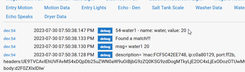
but it never makes it to the Child Water Meter

Does it HAVE to be predefined names or should water work?
The device name “water” is already used for Leak Sensors.
The names are reserved, as they are used to determine which child device type needs to be used.
If you’re trying to add a completely new device type for a Water Meter (instead of a Power Meter), then you’re going to need to come up with a new device name. Perhaps try using “waterMeter” instead of “water”. You’re also going to need to write a custom Child Device driver that implements a “Child Water Meter” with whatever cpbilities/ automation attributes you’d like.
thx for the info... so there is no water meter capability that I could see in SmartThing
Is an attribute sufficient? or do I have to use a capability?
These days, you should be checking Hubitat's documentation for Standard Capabilities, not SmartThings. The Platforms have diverged significantly over the past 5+ years.
Unfortunately, there is no "Water Meter" capability, and thus you'll need to develop a custom driver.
Users cannot create "Capabilities" - only the Hubitat team can do that. However, all you need is custom attribute(s).
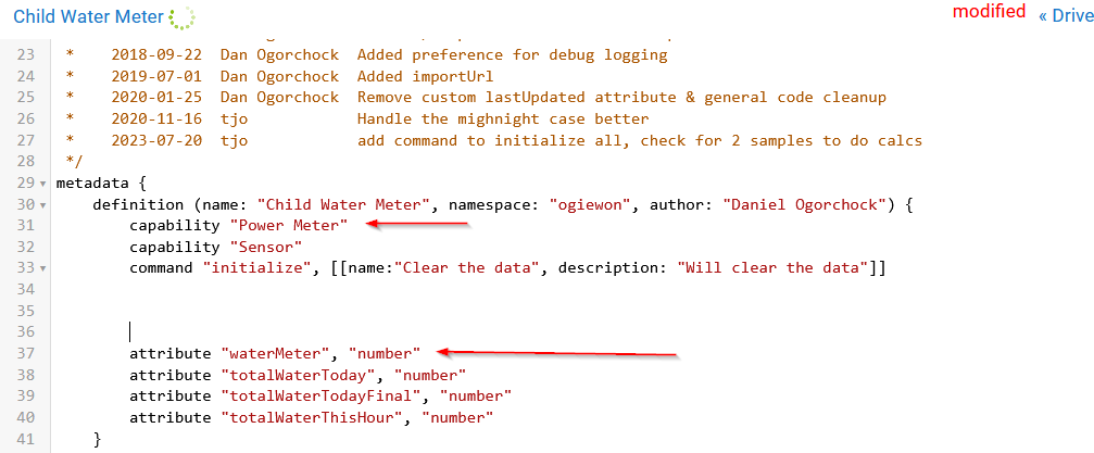
One thing to be careful of, is your custom command called "initialize". "Initialize" is a Standard Capability that already exists. Please change your name to something like 'reset' or 'clearData'. The Initialize Capability implements one command named "initialize()", which conflicts with your custom command.

I would also recommend removing the capability "Power Meter" from your custom child driver. It really serves no purpose if you're writing a custom driver that does not properly implement all of the "Power Meter" commands and attributes.
thanks for your incredible advice ... there is just so much to learn !!
An update for you, Dan, as well as anyone else following this topic on soil sensors...
I did get it working, for the most part. That is, the output values are now rational but I have some more tweaking of the second pair of numbers for the mapping function in order to output to the actual humidity. It is certainly not as straightforward as the Arduino map function but I can probably get it close enough to be usable for my purposes. Just for fun, I even resurrected an ESP8266 version of a sensor I built a couple of years ago and got it working with the Multiples ESP8266WiFi sketch, should I decide to revert back to those devices.
Thanks for all your assistance with this, Dan.
ArtS
That's what is a little odd to me, as it really is the same as the Arduino map() function, but it has been modified to use floating point values instead of simply integer values.
My guess is that your other sample Arduino sketches, were all using 12 bit ADC values from the ESP32. Whereas, my example original example sketch for the ESP32 was configured to use 11 bit ADC values. This obviously makes a huge difference as the min/max for the input side of the map() function are significantly different. This may explain the 'strange' behavior you've observed. Did you modify the ST_Anything_Multiples_ESP32 sketch to configure the ADC to use 12 bits as I mentioned in my earlier post?
Okay, so a few minutes with Excel and I have calculated your map function constants based on your earlier information (i.e. 3500 = 50% AND 3100 = 80%)
Thus, assuming you configure the sketch to use 12 bit resolution for the ADC, simply use the following
static st::PS_Voltage sensor5(F("voltage1"), 10, 0, PIN_VOLTAGE_1, 0, 4095, 312.5, 5.375, 64, 100);
Hope that helps!
I'm finally getting back to this and it took me a bit to figure out where I left off.
Yes, I did change to 12 bit and the ADC values are now different: 50% humidity = 7045 and 100% = 6502. Isn't that beyond the range of a 12 bit number?
In any event, I'm curious about the mapping values you provided. They don't look like what I've done with the Arduino mapping function for my ESP8266 based sensors. Can you share that Excel file?
Yes, 12 bits has a range of 0 to 4095.
I did not save the Excel file. It is a simple slope and offset calculation. Based on the 3500/3100 raw values which you stated mapped to 50%/80% humidity.
A ESP8266 only has a 10 bit ADC, if I recall correctly. So it’s raw range would be 0 to 1024.
I think I understand what I need to do for the 2nd set of values but first, I want to understand why I'm getting those raw values with 12 bits. This ESP32 based sensor is really a black box, as I'm not really sure how the designer uses PWM to generate a voltage for the ADC.
I decided to go back to my Wemos D1 Pro based sensor with the Multiples_ESP8266 code with the because at least I know how things are hooked up. Once I'm confident this is working as I expect, perhaps I'll go back to that other sensor.
The first puzzle I find with this Wemos board is that the value that Hubduino generates differs from what I get with a plain old analog read I placed in the loop.
For example, at 50% reference humidity, I get the following result with an unmapped PS_Voltage call:
static st::PS_Voltage sensor5(F("voltage1"), 10, 1, PIN_VOLTAGE_1);
:
11:38:16.402 -> Average Readings value from 1 samples of analogRead: 592
11:38:16.402 -> Everything: Sending: voltage1 2893.45
Here is my analog read code that produces this:
const unsigned samples = 1;
unsigned int analogVals[samples];
unsigned int counter = 0;
unsigned int total_values = 0;
unsigned int values_avg = 0;
for( counter = 0; counter < samples; counter++){
analogVals[counter] = analogRead(A0);
delay(100);
total_values = (total_values + analogVals[counter]);
}
values_avg = total_values/samples;
Serial.print("Average Readings value from ");
Serial.print(samples);
Serial.print(" samples of analogRead: ");
Serial.println(values_avg);
If I increase the analogRead sample size to 64, it's pretty much the same.
- Any idea why this is so different?
I think I may now see where the confusion is coming from...
The HubDuino PS_Voltage() device ALWAYS utilizes its internal MAP() function. If you do not supply any values, it simply uses default values for the 4 'map' values.
Here is the constructor from PS_Voltage.h with the default values it uses if the user does not supply any...
public:
			//constructor - called in your sketch's global variable declaration section
			PS_Voltage(const __FlashStringHelper *name, unsigned int interval, int offset, byte analogInputPin, double s_l=0, double s_h=1023, double m_l=0, double m_h=5000, int NumSamples=1, byte filterConstant = 100);
As you can see from the above, when I wrote this device I was writing it for the Arduino UNO/MEGA series of boards. The defaults assume a 10bit ADC (0 to 1024) and maps those values to 0-to-5000mV (0 to 5V) which is what the GPIO pins on the original Arduino UNO and MEGA are capable of measuring.
Thus, if you attempt to use the PS_Voltage device without supplying those 4 'map' parameters, you will not get the correct results when using an ESP8266 or an ESP32.
For an ESP8266, the defaults should probably be (0, 1024, 0, 3300) which would make sense for a 10bit ADC that supports voltages from 0 to 3300mV (0 to 3V).
For an ESP32, the values would be dependent on how the ADC is configured in the sketch, as previously mentioned.
- 12 bits = 0, 4095, 0, 3300
- 11 bits = 0, 2047, 0, 3300
- 10 bits = 0, 1024, 0, 3300
- 9 bits = 0, 512, 0, 3300
I hope this clears up the confusion once and for all.
Obviously, since you'd probably prefer a percentage, instead of milliVolts, you can tweak the second pair of parameters for the map function to be whatever you'd like. Just be sure to keep the first pair as shown above, as that indicates the full numeric range of the ADC, based on whatever resolution you set the ESP32's ADC to (12 to 9 bits.)
So, if you really want to see the raw AC value, on an ESP32 with its ADC set to 12 bits, try using the following:
static st::PS_Voltage sensor5(F("voltage1"), 10, 0, PIN_VOLTAGE_1, 0, 4095, 0, 4095, 64, 100);
This will result in no map() function really taking place, and the input and output ranges are set to be the same. It will oversample 64 times before producing an average result, and it will not filter the output whatsoever.
Well that was certainly a breakthrough for me, Dan. Thanks!
Now I understand how those parameters are used ('should have looked into the constructor a long time ago!).
In any event, I have it all working as expected. Now that I know the true input values, I can set the constructor values correctly and get it just the way I want.
I even have the 32bit sensor I purchased working!
Thanks for your patience and dedication to your work Dan !
Art
1 Like
I'm measuring water usage by attaching a hall effect sensor and amplifier to the side of my water meter. When the toilet flushes there is a square wave with a 120ms period.
I'm guessing if I have both garden hoses or the washing machine it would be a smaller period.
I'm using the PS_Pulsecounter code and counting pulses.
I enter a meter reading on the devices page (preferences) and when that is enters it associates that meter reading with the total pulse counts at that time. I have to wait a while then do it again. Once I have 2 readings I calculate how many pulses per gallon.
The issue is that after a few days I'm off quite a bit.
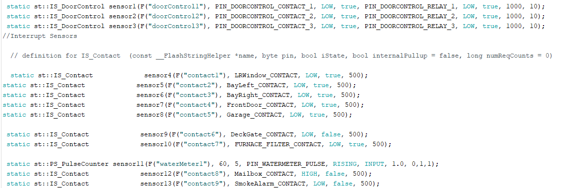
This hubduino application is using an ESP32 and has 13 devices -see below.
My question is whether the issue is PS_Pulsecounter can't keep up, or I have too many devices on the processor or something else ?
Thanks for any help !