I have one more question to you.
Where will be a right place to invert output polarity?
Right now output is set to HIGH when channel is OFF but I need these opposite
because FET Transistors will be used to control LEDs.
And at 100% output still produces a very short pulse instead of being set to LOW
(with current polarity option). This is not a bid deal but could it be (better to be) corrected?
If "yes" please advice what to modify?
OK,
I changed Common Anode settings to false and this took care of both problems.
Now PWM polarity is positive and levels are solid LOW at 0% level and solid HIGH at 100%.
I am all set.
1 Like
Yea, I see that now. Thank you for pointing that out. I did not create this particular example sketch. It was contributed by a SmartThings Community member 6 years ago. Looks like you're the first person to try it since then! ![]()
// 2017-10-08 Allan (vseven) Modified for a RGB LED (single LED or LED strip)
I have fixed the pin assignments in that example sketch. Thanks!
Interesting. But it is what it is. This is exactly what I need for my updated RFID project.
Single Hubduino device will replace battery powered door sensor, Zigbee RGB Controller,
Zigbee Dual Relay and will add RFID Reader capability.
Thank you.
I am sorry to bother you but I was lazy to check pins compatibility docs.
This will remove a confusion for the future potential users (if any will try this).
Vs many ZWave/Zigbee RGB(W) controllers (I did try many but did not like them) this
DIY Hubduino RGB Controller and related HE Driver is far more flexible and intuitive to use.
1 Like
Complex DIY Hubduino project for automating Front Door is complete, debugged and integrated
with HE. This custom controller will replace Door Sensor, 2 Dry Contact Relays, RGB LED Strip
Controller and will add NFC RFID Card Reader support. Smart Phone with NFC (basically any
modern phone) can be used as RFID Tag.
@ogiewon
I still need couple minor improvements (these are not a show stoppers).
- In the Child RGB Driver "Set Color" button is not doing anything. It will be nice to have it
working. I will try to fix it myself but I am not a SW guru and may not find a solution. - Since I am not a SW guru all RFID reader related code simple added at the end of the
void loop(). Everything is working just fine but I am sure, it must be better way to add
new features to the Hubduino.
So, only if you have few spare minutes could you help me with these two issues?
Here is a final (I think) sketch code:
//******************************************************************************************
//
// File: ST_Anything_Relays_ESP8266.ino
// Authors: Dan G Ogorchock & Daniel J Ogorchock (Father and Son)
//
// Summary: This Arduino Sketch, along with the ST_Anything library and the revised SmartThings
//          library, demonstrates the ability of one NodeMCU ESP8266 to
//          implement a multi input/output custom device for integration into SmartThings.
//
//          The ST_Anything library takes care of all of the work to schedule device updates
//          as well as all communications with the NodeMCU ESP8266’s WiFi.
//
//          ST_Anything_Relays_ESP8266 implements the following ST Capabilities as a demo of what is possible with a single NodeMCU ESP8266
//            - 3 x Relay Switch devices
//
//
// Change History:
//
//    Date        Who            What
//    ----        ---            ----
//    2015-01-03  Dan & Daniel   Original Creation
//    2017-02-12  Dan Ogorchock  Revised to use the new SMartThings v2.0 library
//    2017-04-17  Dan Ogorchock  New example showing use of Multiple device of same ST Capability
//                               used with new Parent/Child Device Handlers (i.e. Composite DH)
//    2017-05-25  Dan Ogorchock  Revised example sketch, taking into account limitations of NodeMCU GPIO pins
//    2017-11-27  Kai Lenk       Modified to 3 relaySwitch
//    2017-11-29  Dan Ogorchock  Revisions to make sure works for Kai Lenk
//    2018-02-09  Dan Ogorchock  Added support for Hubitat Elevation Hub
//
//******************************************************************************************
//******************************************************************************************
// SmartThings Library for ESP32WiFi
//******************************************************************************************
#include <SmartThingsESP32WiFi.h>

//******************************************************************************************
// ST_Anything Library
//******************************************************************************************
#include <Constants.h>         //Constants.h is designed to be modified by the end user to adjust behavior of the ST_Anything library
#include <Device.h>            //Generic Device Class, inherited by Sensor and Executor classes
#include <Sensor.h>            //Generic Sensor Class, typically provides data to ST Cloud (e.g. Temperature, Motion, etc…)
#include <Executor.h>          //Generic Executor Class, typically receives data from ST Cloud (e.g. Switch)
#include <InterruptSensor.h>   //Generic Interrupt "Sensor" Class, waits for change of state on digital input
#include <PollingSensor.h>     //Generic Polling "Sensor" Class, polls Arduino pins periodically

#include <IS_Button.h>         //Implements an Interrupt Sensor (IS) to monitor the status of a digital input pin for button presses
#include <IS_Contact.h>        //Implements an Interrupt Sensor (IS) to monitor the status of a digital input pin
#include <EX_Switch.h>         //Implements an Executor (EX) via a digital output to a relay
#include <EX_RGB_Dim.h>        //Implements an Executor (EX) for a RGB LED or strip with PWM using 3 digital output pins

#include <Everything.h>        //Master Brain of ST_Anything library that ties everything together and performs ST Shield communications

// For the RC522 RFID Reader
#include <SPI.h>
#include <MFRC522.h>

//*************************************************************************************************

// WiFi Credentials
#include "credentials.h"

//*************************************************************************************************

// ESP32 WDOOM IO Pins

// Contact Sensor
#define IN_SENSOR_1     14

// Dry Contact Relay
#define OUT_RELAY_1     16
#define OUT_RELAY_2     17

// RGB LEDs
#define OUT_RGB1_Red    25
#define OUT_RGB1_Green  26
#define OUT_RGB1_Blue   27

// CR522 RFID Reader
#define SS_PIN          5
#define RST_PIN         21

// All standard ESP32 SPI Pins are used in addition
// MOSI GPIO23
// MISO GPIO19
// CLK  GPIO18

// Instantiate RC522 RFID Reader
MFRC522 rfid(SS_PIN, RST_PIN);

//******************************************************************************************
//Define which Arduino Pins will be used for each device
//******************************************************************************************

#define PIN_CONTACT_1      IN_SENSOR_1      //Hubitat Capabilities - DIO Pin (Normally Open!)

#define PIN_RELAY_1        OUT_RELAY_1      //SmartThings Capability "Relay Switch"
#define PIN_RELAY_2        OUT_RELAY_2      //SmartThings Capability "Relay Switch"

#define PIN_RGB1_Red       OUT_RGB1_Red
#define PIN_RGB1_Green     OUT_RGB1_Green
#define PIN_RGB1_Blue      OUT_RGB1_Blue

//******************************************************************************************
//ESP832 WiFi Information
//******************************************************************************************

// Set your WiFi details so the board can connect to the WiFi and Internet

// Get Credentials from the credentials.h file
const char* str_ssid     = mySSID;
const char* str_password = myPASSWORD;

IPAddress ip        (192, 168,  20, 151);  // Device IP Address       //  <---You must edit this line!
IPAddress gateway   (192, 168,  20,   1);  // Router Gateway          //  <---You must edit this line!
IPAddress subnet    (255, 255, 255,   0);  // LAN Subnet Mask         //  <---You must edit this line!
IPAddress dnsserver (192, 168,  20,   1);  // DNS Server              //  <---You must edit this line!
const unsigned int  serverPort = 8090;     // Port to run the HTTP Server on

// Hubitat Hub TCP/IP Address
IPAddress hubIp     (192, 168, 20,   90);  // Hubitat Hub IP          //  <---You must edit this line!

// Hubitat Hub TCP/IP Address
const unsigned int hubPort = 39501;        // Hubitat Nub Port

//******************************************************************************************
//st::Everything::callOnMsgSend() optional callback routine.  This is a sniffer to monitor
//    data being sent to ST.  This allows a user to act on data changes locally within the
//    Arduino sktech.
//******************************************************************************************
void callback(const String &msg)
{
//  Serial.print(F("ST_Anything Callback: Sniffed data = "));
//  Serial.println(msg);

  //TODO:  Add local logic here to take action when a device's value/state is changed

  //Masquerade as the ThingShield to send data to the Arduino, as if from the ST Cloud (uncomment and edit following line)
  //st::receiveSmartString("Put your command here!");  //use same strings that the Device Handler would send
}

//-------------------------------------------------------------------------------

// Variables for integration with Hubitat
String str_Card_ID;
String msg_Card_ID;
unsigned int cardCode;

//******************************************************************************************
//Arduino Setup() routine
//******************************************************************************************

void setup()
{
  //******************************************************************************************
  //Declare each Device that is attached to the Arduino
  //  Notes: - For each device, there is typically a corresponding "tile" defined in your
  //           SmartThings Device Hanlder Groovy code, except when using new COMPOSITE Device Handler
  //         - For details on each device's constructor arguments below, please refer to the
  //           corresponding header (.h) and program (.cpp) files.
  //         - The name assigned to each device (1st argument below) must match the Groovy
  //           Device Handler names.  (Note: "temphumid" below is the exception to this rule
  //           as the DHT sensors produce both "temperature" and "humidity".  Data from that
  //           particular sensor is sent to the ST Hub in two separate updates, one for
  //           "temperature" and one for "humidity")
  //         - The new Composite Device Handler is comprised of a Parent DH and various Child
  //           DH's.  The names used below MUST not be changed for the Automatic Creation of
  //           child devices to work properly.  Simply increment the number by +1 for each duplicate
  //           device (e.g. contact1, contact2, contact3, etc...)  You can rename the Child Devices
  //           to match your specific use case in the ST Phone Application.
  //******************************************************************************************

  //Polling Sensors

  //Interrupt Sensors
  // Name, IO Pin, Initial State, Internal Pullup, Number of Loop Counts
  static st::IS_Contact sensor1(F("contact1"), PIN_CONTACT_1, LOW, true, 20);

  //EX_Switch arguments(Name, Pin, Initial State, Invert Logic) change last 2 args as needed for your application
  static st::EX_Switch executor1(F("switch1"), PIN_RELAY_1, LOW, true);
  static st::EX_Switch executor2(F("switch2"), PIN_RELAY_2, LOW, true);

  // RGB Dimmer
  static st::EX_RGB_Dim executor3(F("rgbSwitch1"), PIN_RGB1_Red, PIN_RGB1_Green, PIN_RGB1_Blue, false, 0, 1, 2); // channels (0,1,2) must be unique per ESP32

  //*****************************************************************************
  //  Configure debug print output from each main class
  //  -Note: Set these to "false" if using Hardware Serial on pins 0 & 1
  //         to prevent communication conflicts with the ST Shield communications
  //*****************************************************************************
  st::Everything::debug      = true;
  st::Executor::debug        = true;
  st::Device::debug          = true;
  st::PollingSensor::debug   = true;
  st::InterruptSensor::debug = true;

  //*****************************************************************************
  //Initialize the "Everything" Class
  //*****************************************************************************

  //Initialize the optional local callback routine (safe to comment out if not desired)
  st::Everything::callOnMsgSend = callback;

  //Create the SmartThings ESP32WiFi Communications Object
    //STATIC IP Assignment - Recommended
    st::Everything::SmartThing = new st::SmartThingsESP32WiFi(str_ssid, str_password, ip, gateway, subnet, dnsserver, serverPort, hubIp, hubPort, st::receiveSmartString);

    //DHCP IP Assigment - Must set your router's DHCP server to provice a static IP address for this device's MAC address
    //st::Everything::SmartThing = new st::SmartThingsESP8266WiFi(str_ssid, str_password, serverPort, hubIp, hubPort, st::receiveSmartString);

  //Run the Everything class' init() routine which establishes WiFi communications with SmartThings Hub
  st::Everything::init();

  //*****************************************************************************
  //Add each sensor to the "Everything" Class
  //*****************************************************************************
  st::Everything::addSensor(&sensor1);

  //*****************************************************************************
  //Add each executor to the "Everything" Class
  //*****************************************************************************
  st::Everything::addExecutor(&executor1);
  st::Everything::addExecutor(&executor2);
  st::Everything::addExecutor(&executor3);

  //*****************************************************************************
  //Initialize each of the devices which were added to the Everything Class
  //*****************************************************************************
  st::Everything::initDevices();

  // Fot the RC522 RFID Reader
  Serial.begin(115200);  // Serial Port Baud Rate
  SPI.begin();           // Init SPI bus
  rfid.PCD_Init();       // Init MFRC522

  Serial.println("Tap an RFID/NFC tag on the RFID-RC522 reader");
}

//*******************************************************************************
//Arduino Loop() routine
//*******************************************************************************

void loop()
{
  //*****************************************************************************
  //Execute the Everything run method which takes care of "Everything"
  //*****************************************************************************

  st::Everything::run();

  //*****************************************************************************
  //Read RFID Tag
  //*****************************************************************************

  if (rfid.PICC_IsNewCardPresent()) // New Tag is available
  {
    if (rfid.PICC_ReadCardSerial()) // NUID has been readed
    {
      MFRC522::PICC_Type piccType = rfid.PICC_GetType(rfid.uid.sak);
      Serial.print("RFID/NFC Tag Type: ");
      Serial.println(rfid.PICC_GetTypeName(piccType));

      // print UID in Serial Monitor in the hex format
      Serial.print("UID:");
      for (int i = 0; i < rfid.uid.size; i++)
      {
        Serial.print(rfid.uid.uidByte[i] < 0x10 ? " 0" : " ");
        Serial.print(rfid.uid.uidByte[i], HEX);
      }
      Serial.println();

      // Reset cardCode
      cardCode = 0;

      // Combine Bytes into single Word
      // Only last 4 Bytes (32 Bits) will be used as a Card ID Code
      for (int i = 0; i < rfid.uid.size; i++)
      {
        cardCode = ((cardCode << 8) + rfid.uid.uidByte[i]);
      }

      rfid.PICC_HaltA();      // halt PICC
      rfid.PCD_StopCrypto1(); // stop encryption on PCD

      // Send a Valid Card ID to Hubitat
      str_Card_ID = String(cardCode, DEC);
      msg_Card_ID = "voltage1 " + str_Card_ID;
      st::Everything::sendSmartString(msg_Card_ID);

      // Send Trigger Event to the Hubitat
      st::Everything::sendSmartString("button1 pushed");
    }
  }
  //*****************************************************************************
}
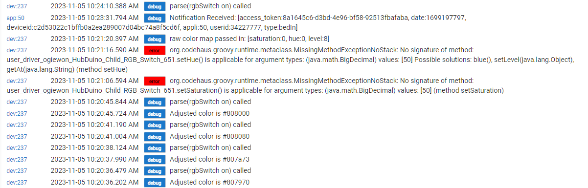
Here is an error from RGB Child:
UPDATE
RGB Child Component is not working as expected.
On, Off, All preset colors buttons are working just fine.
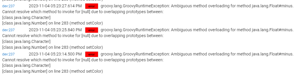
Set Color, Set Saturation and Set Hue buttons are not working and producing Java Errors:
There is no way I can fix this myself (not enough programming skills).
Ideally I would like to see a Button for the direct RGB settings say, in hex format 0xRRGGBB
I am sure, this could be added relatively easy.
@ogiewon
For passing 32-bit RFID code per yours suggestion long time ago I am using
"child-voltage-sensor.groovy" child device driver. Messages from Hubdiono on Serial Port
always showing a correct RFID number passed to the HE. However (and somehow this depend
on actual integer value) Voltage is not updating and stuck with old value. This happens when
Number of Decimal Places is set to 0. If it is not 0 than everything is correct however dealing with
this floating numbers becomes tricky. Looking at "child-voltage-sensor.groovy" code I cannot
even imagine how it may fail if number of decimal places is set to 0.
What I am missing here?
Is it any better (more native and elegant) way to pass 32-bit (actually 64-bit will be even better
because some RFID tags are sending 7 or even 10 bytes, but sure, 32-bit (4 bytes) is OK) value
to the HE whatever child driver?
Just take the Child Voltage driver, make a copy of it, and give it a new name. Then modify the code however you see fit. Then, change the driver type of your existing RFID child device to use the new one. This gives you the flexibility to mess around with the code as much as you’d like, without impacting any of your other Child Voltage devices.
Well, I am thinking hard to take this approach. But I have one BIG obstacle - my SW experience
with all these modern/new languages like Groovy is "one way ticket". I.e. I can more or less clearly
understand whatever already written but when it time to modify something, ops - I don't know
what functions are already exist, which parameters to use, etc, etc, ... etc.
Very good example is this "voltage child device". I looked at this code for hours and could not
understand why it failing the way I am observing. To my eyes it should work just fine but it
does not. So, how can I modify this code if the existing one looks good?
Plus I cannot clearly understand how to debug something in the HE environment.
It seems like the only debugging option is to stick logs left and right.
There is not much code in the Child Voltage driver. Simply enable the logging so you can see exactly what is sent from the microcontroller and is being “parsed” by the driver.
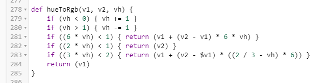
You will then see this section of code
if (name && value) {
54
        if (numDecimalPlaces == null) {
55
            device.updateSetting("numDecimalPlaces", [value: "1", type: "enum"])
56
        }
57

58
        if (numDecimalPlaces == "0") {
59
            int tmpValue = Float.parseFloat(value)
60
            sendEvent(name: name, value: tmpValue, unit: "V")
61
        }
62
        else {
63
            float tmpValue = Float.parseFloat(value)
64
            tmpValue = tmpValue.round(numDecimalPlaces.toInteger())
65
            sendEvent(name: name, value: tmpValue, unit: "V")
66
        }
67
    }
68
    else {
69
        log.error "Missing either name or value.  Cannot parse!"
70
    }
My guess is that the RFID “value” is not an actual floating point number, correct? If so, then simply eliminate the code that deals with converting the ‘value’ into a float, and the associated rounding.
Groovy is pretty simple. And 5he above code is pretty easy to read, IMHO. Give it a shot. You’ll probably surprise yourself with how easy it is to make simple changes.
Your code will probably just need
sendEvent(name: name, value: value)
Which eliminates all of the decimal place rounding code.
What does the RFID “value” look like? Provide an example.
RFID is a byte array with usually 4 bytes, some tags will send 7 bytes and even 10 bytes is possible.
Here is screen shot prom hubduino serial terminal:
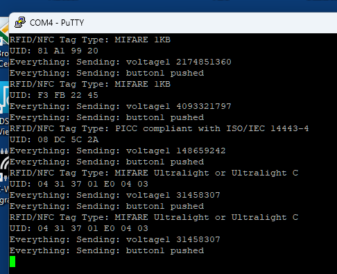
UID: is a RFID Code from reader.
First two UIDs are from regularMUFAIR tags.
Third one is from my Android Phone.
These are 4 bytes (32-bit) unsinged integers.
Last two are from advanced MIFARE Tags (the same tag scanned twice) and its code is
7 bytes long. There are even tags with 10 bytes code.
From the Hubduino I am sending only last 4 bytes of whatever RFID code is.
First - 4 bytes should be more than enough and second - I don't want to deal with
lolg long (ie. 64-bit) integers on the Hubduino/Arduino side.
Bottom line - Hubduino always sends a correct 32-bit unsinged integer to the HE.
And yes, all what I need is to get this integer to the RM Rule whichever way is more
appropriate.
I will try to modify voltage child driver according to yours suggestions and see
what happens. But I am really surprised to see the existing child voltage driver
very strange behavior. Somehow it fails to pass/get current value and shows older
(but not lates older) value. From the driver code I don't see how this even possible.
OK, from the existing driver I removed everything but left the suggested line of code.
So far so good. Everything seems to be working as expected. I need more testing
because at the begging the original driver worked just fine but suddenly started his
very strange behavior without any apparent reasons. Let me see how stable this
stripped version will go.
Ho do I modify Parent Driver so it will create an appropriate Child Driver?
Another words where is a source for the "deviceName" variable?
try {
def deviceHandlerName = ""
switch (deviceName) {
case "contact":
deviceHandlerName = "HubDuino Child Contact Sensor"
break
case "switch":
deviceHandlerName = "HubDuino Child Switch"
Hey, I noticed this and wanted to comment. I've been trying to work out a keypad/card reader. After poking around I'm probably going to try the ESPhome Wiegand component and work out a hubitat ESPhome driver from the other examples. I'm looking at the WESP32 with POE.
I have working Hubduino sketch for readers with Wiegand interface. Unfortunately this
readers are big in size. I am in apartment complex and management is not happy if
something is installed on the walls outside the apartment. RC522 reader is small and
I am planning to hide it behinde apartment number plate. Plus this reader can read
smart phone NFC ID code. My building is using HID Tags for building and/or elevators
access. I am planning to use dual technology RFID tags so single tag will give an access
to building, elevators and my apartment. This project is near 100% complete.
All programming is done. Now I have to put together all parts on a single board.
That originates on the Arduino side of things. Instead of “voltage1”, use something like “rfid1”, and then add a case entry for “rfid” to create a child using your new Child Driver.
Well, this works but unfortunately cannot be used.
I made all the suggested changes.
The related child device was created and all drivers are working as expected.
The "Current States" reported "rfid" attribute:

However this attribute immedietly disappears and there fore cannot be used:

I think, this is something to do with declared "capability".
"rfid" attribute does not exist and simply ignored by HE platform.
Is it any way to correct this without requesting to add ne capability?
Otherwise i will have to mess up with existing "Voltage Measurement" capability.
This will work but becomes very messy work around and better to be avoided.
Yes, just add "rfid" as a custom attribute near the top of the driver:
something like the following:
metadata {
	definition (name: "Child RFID Sensor", namespace: "ogiewon", author: "Daniel Ogorchock") {
		capability "Sensor"

        attribute "rfid", "number"
	}
Yes, this did a trick and fixed a problem.
(BTW, I already find this out by searching Hubitat forum for dealing with custom attribute.
But anyway, very BIG Thank you for all your help and support.)
However I found a bug or at least inconsistency.
After I modified a child driver to send out voltage as a an integer all values were offset by -1.
Another words, it looks like LSB in the 32bit integer always was 0.
The 32bit RFID code from RC522 RFID reader sent to HE always was correct (and just in case
I verified the HEX Tag Value by independent RFID reader). I have a test RM rule which checks
code from reader vs. valid User Codes. When I created a local variables holding a valid user
codes I simply cut-and-paste values from the device page. Once I changed my(yours) modified
driver to use custom "rfid" attribute all user rfid codes became invalid. All they are offset by -1.
I am not sure why this was happening and were is a source for the problem.
But obviously there is a bug somewhere and better to be corrected.
And here is one little problem better to be corrected.
For some reason "Set Color" button for the RGB Child Component is not working and prodices
an error:

Error points to line 283 I think, in the RGB child driver but to my eyes it makes no sense:
For my application this is not a show stopper (I certainly can use pre-defined colors
and if necessary to modify them or even add more) but this problem better to be corrected.
Nano 33 IoT with connected DS18B20 temp probe ?
Objective – Four(4) separate non-wired temperature locations.
HubDuino Hubitat to Arduino app/driver will work as below?
Install four occurrences of HubDuino (4) and four(4) separate Nano 33 IoTs to reach non-wired locations. Or can one (1) HubDuino network with several Nano 33 IoTs?
Four (4) occurrences of “Temperature Measurement (using Dallas Semiconductor DS18B20's, requires OneWire and DallasTemperature libraries included in this repo)”
Is there a lower cost method than using Arduino Nano 33 IoT with DS18B20 temp probe since needing only one sensor per Nano 33 IoT and HubDuino.
Thanks, Jerry
Should be possible, but I have not personally tested that exact combination.
Is there any reason for choosing the Nano 33 Iot microcontroller versus an ESP8266 or ESP32 based microcontroller? Both of the ESP boards have had a lot more testing and real-world applications of HubDuino.
Each microcontroller requires its own "HubDuino Parent Ethernet" device to be manually created on the Hubitat hub. Each microcontroller will needs its own TCP/IP address.
Sure, this should work. But as I mentioned earlier, I do not recall testing this specific hardware combination. I do use an NodeMCU ESP8266 microcontroller to monitor 4 DS18B20 temperature sensors without any issues.
It depends on what you want to measure with these DS18B20 sensors. Please share more about your particular project and its goals.
As mentioned earlier, one microcontroller can monitor more than 1 DS18B20 sensor, assuming the wiring is not an issue. Obviously, if you want these 4 sensors spread out across different parts of your house, then you would want to use one microcontroller per temperature sensor.
As for a lower cost solution? Again, it depends on what exactly you're wanting to measure the temperatures of. I have Zigbee motion control and leak sensors all over my house. Each of these reports temperature as an added bonus. The batteries last for about 12-24 months. So, that might be an option for you. The Nano 33 IoT will require constant USB power plugged into the mains power.

