What is the correct way to delete an HPE parent child device?
I installed Hubduino September 2019 and successfully added 3 dsb18b20 temperature sensors monitoring attic temperature on an esp8266 NodeMCU. All the child devices available at that time were created in Hubitat. In order to reduce clutter I would like to remove all child devices not being used.
Also device logging indicates % busy time for HPE parent is 57.6%. I’m not sure if this is a problem but reducing unnecessary work for processor is always a good thing.
An alert indicates database is at 189m and growing and suggested reducing history event and state history limits might help. These history items were reduced for HPE parent to 50/15 but don’t yet know what effect if any this have.
Current configuration = C5 and ver 2,3.0.120
Any and all comments would be much appreciated.
Did you remove the “extra” devices from the Arduino sketch already? That would be the first step, as otherwise they will just keep coming back. Once you have cleaned up the sketch, compiled it, and uploaded it to the microcontroller, you can simple delete any extraneous child devices. To do so, simply open the device details page for each extra child device, then click REMOVE near the bottom of the page.
Great - Glad to hear the answer from the Hubduino master. I will implement the removals shortly.
Would still like to hear comment about the 57.6% busy time for HPE parent. Is that typical for Hubduino? I had planned to add another NodeMCU for another project. Would adding 2nd NodeMCU overload Hubitat or am I misinterpreting the device log entry.
Thanks Ogiewon for your reply.
That would depend greatly on the overall load on your hub, as the 57.6% might be nothing to be too concerned about if your hub isn’t very busy to begin with. However, if you’ve set your sketch’s poll rates to collect temperature data every 5 seconds, that might explain the excessive busy time? Hard to say without understanding exactly how you have things configured. ![]()
Depends on what the 57.6% is in relation to. If it is of total busy, and total busy is low, then no issue; i.e. 57% of 5% total available is 2.85% of total available or practically sleeping.
I'm trying to make an updated shade controller...that supports an optional open and close switches and timers and a motor controller and I'm confused on how to handle the open and close switch .....looking at other code it appears that the code inherits from InterruptSensor and there is runInterrupt and runInterruptEnded functions.... but not sure how to tie it together...especially when there is 2 switches....
Here is the code if someone smart could look at and give any advice...
note i wasn't sure how to share code ...so hoping github will work...
Any suggestions...words of wisdom ?
Well, I was hoping maybe someone else would chime in with their experiences in trying to build a DIY Window Shade Controller. Since I have never built one, nor do I have the need for such a device in my home (all plantation shutters here, which my wife loves, and there is no way to automate easily), I really have never given it much thought.
If you already have a working Arduino Sketch, then perhaps you could simply integrate it directly with Hubitat?
- What commands do you want Hubitat to be able to send to the Arduino?
- What data do you want Hubitat to be able to receive from the Arduino?
Getting things down to the basic requirements often helps to design a simple solution. IF your existing sketch works well, then please consider simply adding the "SmartThings..." communications library to it, to enable two-way communications with Hubitat. Within the main "SmartThings" library in my repo, you'll find an example sketch (free of all of the other ST_Anything libraries and code.) ST_Anything uses these exact same "SmartThings..." libraries for its communications with Hubitat.
If you search through the vast number of posts within the SmartThings ST_Anything thread, as well as the Hubitat HubDuino thread, you'll see that I have avoided the whole stepper motor problem entirely, as it requires a lot more programming to make a safe, reliable, robust 'motion control' system than I have time for. Especially, since it is not something that I have a need for, unfortunately. I wish I had more to offer you. I truly wish you the best of luck in your project.
I appreciate you piping in... I know we all rely too heavily on you.
the commands needed are really open and close ..i had stop in there but not necessary
i want hubitat to receive status (i.e. opened, opening,closed,closing,unknown)
fyi, its just an analog motor controller, forward or reverse at a given speed...really simple
inputs are Forward,reverse and analog speed (done w PWM output).
My desire to adopt your architecture stems from wanting to add additional sensors to that 8266 ( motion and light) and your architecture does an amazing job of that..
My single esp32 has 12 child devices, 3 garage door combos,5 door switches (contacts), 1 water meter, 1 scale,1 furnace indicator, 1 mailbox switch ...all by adding a few lines of code for each....pretty neat
I guess I could try what you suggested...but i think i am close .. if I could only understand how to tie the switches into the code...
Whats puzzling is that the Shade code inherits from InterruptSensor ....which implies I think that there is only 1 switch allowed vs having member data that is a InterruptSensor in which case I could have several.
the switches do not need to be exposed to hubitat so can/should I ditch inheriting from InterruptSensor and do the checking of the switches when update is periodically called?
sorry but confused in MN
Yes, you can add whatever arguments you’d like to the constructor, including whatever pins you’d like to monitor. You can then override the default InterruptSensor’s methods if you’d like (it’s all C++ after all ![]() ) and monitor the two pins in your own code, and take whatever action internally you’d like to do. That is what’s great about HubDuino - it is really up to the user to do with it as they see fit. Glad to hear you’re finding it useful.
) and monitor the two pins in your own code, and take whatever action internally you’d like to do. That is what’s great about HubDuino - it is really up to the user to do with it as they see fit. Glad to hear you’re finding it useful.
I am just now discovering HubDuino. I have added the libraries to my arduino IDE and added all the drivers in the Hubitat section. I am able to load a sketch for Illuminance as the detector. I fill in my wifi details and ip addresses, however, it never joins the network.
So, I dropped back, got a basic sketch for NodeMCU ESP8266 and compiled that sketch with wifi information and it connected to the network. So obviously I'm missing something for ST_Anything to connect, even though the compile in arduino doesn't present any errors.
Can anyone please take a few minutes to educate me on how this system works. All I am trying to do is a simple LDR light sensor on input A0.
Thank you!!
Sure, happy to help. But need a lot more details in order to assist. For example, what to you see in the Arduino IDE’s Serial Monitor window?
Thank you.. I was able to get the wifi to work. something from the example sketch was not setup correct in the the one I'm using, so I just copied that entire part over to the other sketch and it joined. Below is the sketch. But I never see anything on the Hubitat side, I did verify the correct port number different from the ST hub. Also, I added every child driver from the import RAW on GitHub under Hubitat.
It says its suppose to automatically create a child device from the parent. I do not see how this is possible without any app code running the the hubitat.

//******************************************************************************************
// File: ST_Anything_Multiples_ESP8266WiFi.ino
// Authors: Dan G Ogorchock & Daniel J Ogorchock (Father and Son)
//
// Summary: This Arduino Sketch, along with the ST_Anything library and the revised SmartThings
// library, demonstrates the ability of one NodeMCU ESP8266 to
// implement a multi input/output custom device for integration into SmartThings.
// The ST_Anything library takes care of all of the work to schedule device updates
// as well as all communications with the NodeMCU ESP8266's WiFi.
//
// ST_Anything_Multiples implements the following ST Capabilities as a demo of what is possible with a single NodeMCU ESP8266
// - 1 x Alarm device (using a simple digital output)
// - 1 x Contact Sensor devices (used to monitor magnetic door sensors)
// - 1 x Switch devices (used to turn on a digital output (e.g. LED, relay, etc...)
// - 1 x Motion devices (used to detect motion)
// - 1 x Smoke Detector devices (using simple digital input)
// - 1 x Temperature Measurement devices (Temperature from Dallas Semi 1-Wire DS18B20 device)
// - 1 x Relay Switch devices (used to turn on a digital output for a set number of cycles And On/Off times (e.g.relay, etc...))
// - 2 x Button devices (sends "pushed" if held for less than 1 second, else sends "held"
// - 1 x Water Sensor devices (using the 1 analog input pin to measure voltage from a water detector board)
//
// Change History:
//
// Date Who What
// ---- --- ----
// 2015-01-03 Dan & Daniel Original Creation
// 2017-02-12 Dan Ogorchock Revised to use the new SMartThings v2.0 library
// 2017-04-17 Dan Ogorchock New example showing use of Multiple device of same ST Capability
// used with new Parent/Child Device Handlers (i.e. Composite DH)
// 2017-05-25 Dan Ogorchock Revised example sketch, taking into account limitations of NodeMCU GPIO pins
//
//******************************************************************************************
//******************************************************************************************
// SmartThings Library for ESP8266WiFi
//******************************************************************************************
#include <SmartThingsESP8266WiFi.h>
//******************************************************************************************
// ST_Anything Library
//******************************************************************************************
#include <Constants.h> //Constants.h is designed to be modified by the end user to adjust behavior of the ST_Anything library
#include <Device.h> //Generic Device Class, inherited by Sensor and Executor classes
#include <Sensor.h> //Generic Sensor Class, typically provides data to ST Cloud (e.g. Temperature, Motion, etc...)
#include <Executor.h> //Generic Executor Class, typically receives data from ST Cloud (e.g. Switch)
#include <InterruptSensor.h> //Generic Interrupt "Sensor" Class, waits for change of state on digital input
#include <PollingSensor.h> //Generic Polling "Sensor" Class, polls Arduino pins periodically
#include <Everything.h> //Master Brain of ST_Anything library that ties everything together and performs ST Shield communications
#include <PS_Illuminance.h> //Implements a Polling Sensor (PS) to measure light levels via a photo resistor
//*************************************************************************************************
//NodeMCU v1.0 ESP8266-12e Pin Definitions (makes it much easier as these match the board markings)
//*************************************************************************************************
#define PIN_ILLUMINANCE_1 A0
//#define LED_BUILTIN 16
//#define BUILTIN_LED 16
//
//#define D0 16 //no internal pullup resistor
//#define D1 5
//#define D2 4
//#define D3 0 //must not be pulled low during power on/reset, toggles value during boot
//#define D4 2 //must not be pulled low during power on/reset, toggles value during boot
//#define D5 14
//#define D6 12
//#define D7 13
//#define D8 15 //must not be pulled high during power on/reset
//******************************************************************************************
//Define which Arduino Pins will be used for each device
//******************************************************************************************
//******************************************************************************************
//ESP8266 WiFi Information
//******************************************************************************************
String str_ssid = "myssid"; // <---You must edit this line!
String str_password = "mypasswd"; // <---You must edit this line!
IPAddress ip(192, 168, 68, 133); //Device IP Address // <---You must edit this line!
IPAddress gateway(192, 168, 68, 1); //Router gateway // <---You must edit this line!
IPAddress subnet(255, 255, 255, 0); //LAN subnet mask // <---You must edit this line!
IPAddress dnsserver(192, 168, 68, 1); //DNS server // <---You must edit this line!
const unsigned int serverPort = 8090; // port to run the http server on
// Smarthings Hub Information
//IPAddress hubIp(192, 168, 68, 125); // smartthings hub ip // <---You must edit this line!
//const unsigned int hubPort = 39500; // smartthings hub port
// Hubitat Hub Information
IPAddress hubIp(192, 168, 1, 125); // hubitat hub ip // <---You must edit this line!
const unsigned int hubPort = 39501; // hubitat hub port
//******************************************************************************************
//st::Everything::callOnMsgSend() optional callback routine. This is a sniffer to monitor
// data being sent to ST. This allows a user to act on data changes locally within the
// Arduino sktech.
//******************************************************************************************
void callback(const String &msg)
{
//Serial.print(F("ST_Anything Callback: Sniffed data = "));
//Serial.println(msg);
//TODO: Add local logic here to take action when a device's value/state is changed
//Masquerade as the ThingShield to send data to the Arduino, as if from the ST Cloud (uncomment and edit following line)
//st::receiveSmartString("Put your command here!"); //use same strings that the Device Handler would send
}
//******************************************************************************************
//Arduino Setup() routine
//******************************************************************************************
void setup()
{
//******************************************************************************************
//Declare each Device that is attached to the Arduino
// Notes: - For each device, there is typically a corresponding "tile" defined in your
// SmartThings Device Hanlder Groovy code, except when using new COMPOSITE Device Handler
// - For details on each device's constructor arguments below, please refer to the
// corresponding header (.h) and program (.cpp) files.
// - The name assigned to each device (1st argument below) must match the Groovy
// Device Handler names. (Note: "temphumid" below is the exception to this rule
// as the DHT sensors produce both "temperature" and "humidity". Data from that
// particular sensor is sent to the ST Hub in two separate updates, one for
// "temperature" and one for "humidity")
// - The new Composite Device Handler is comprised of a Parent DH and various Child
// DH's. The names used below MUST not be changed for the Automatic Creation of
// child devices to work properly. Simply increment the number by +1 for each duplicate
// device (e.g. contact1, contact2, contact3, etc...) You can rename the Child Devices
// to match your specific use case in the ST Phone Application.
//******************************************************************************************
//Polling Sensors
//static st::PS_Water sensor1(F("water1"), 60, 20, PIN_WATER_1, 200);
//static st::PS_DS18B20_Temperature sensor2(F("temperature1"), 15, 0, PIN_TEMPERATURE_1, false, 10, 1);
//***********************************************
static st::PS_Illuminance sensor1(F("illuminance1"), 60, 20, PIN_ILLUMINANCE_1, 0, 1023, 0, 1000);
//*************************************************
//*****************************************************************************
// Configure debug print output from each main class
// -Note: Set these to "false" if using Hardware Serial on pins 0 & 1
// to prevent communication conflicts with the ST Shield communications
//*****************************************************************************
st::Everything::debug = true;
st::Executor::debug = true;
st::Device::debug = true;
st::PollingSensor::debug = true;
st::InterruptSensor::debug = true;
//*****************************************************************************
//Initialize the "Everything" Class
//*****************************************************************************
//Initialize the optional local callback routine (safe to comment out if not desired)
st::Everything::callOnMsgSend = callback;
//Create the SmartThings ESP8266WiFi Communications Object
//STATIC IP Assignment - Recommended
st::Everything::SmartThing = new st::SmartThingsESP8266WiFi(str_ssid, str_password, ip, gateway, subnet, dnsserver, serverPort, hubIp, hubPort, st::receiveSmartString, "BedroomESP");
//DHCP IP Assigment - Must set your router's DHCP server to provice a static IP address for this device's MAC address
//st::Everything::SmartThing = new st::SmartThingsESP8266WiFi(str_ssid, str_password, serverPort, hubIp, hubPort, st::receiveSmartString, "BedroomESP");
//Run the Everything class' init() routine which establishes WiFi communications with SmartThings Hub
st::Everything::init();
//*****************************************************************************
//Add each sensor to the "Everything" Class
//*****************************************************************************
st::Everything::addSensor(&sensor1);
//*****************************************************************************
//Initialize each of the devices which were added to the Everything Class
//*****************************************************************************
st::Everything::initDevices();
}
//******************************************************************************************
//Arduino Loop() routine
//******************************************************************************************
void loop()
{
//*****************************************************************************
//Execute the Everything run method which takes care of "Everything"
//*****************************************************************************
st::Everything::run();
}
Well, I can assure you that an App is not necessary to create child devices. The Parent Device will create the child devices once properly formatted data is received from the microcontroller.
Logs from the Hubitat side and the Arduino side would really be helpful to see.
Are you sure your hub’s IP address is correct in the sketch?
Looks like you have it as 192.168.1.125? Should it be 192.168.68.125?
that would be an error... i guess i put it in correctly before the copy over of that section and carelessly didnt change the 3rd octet.
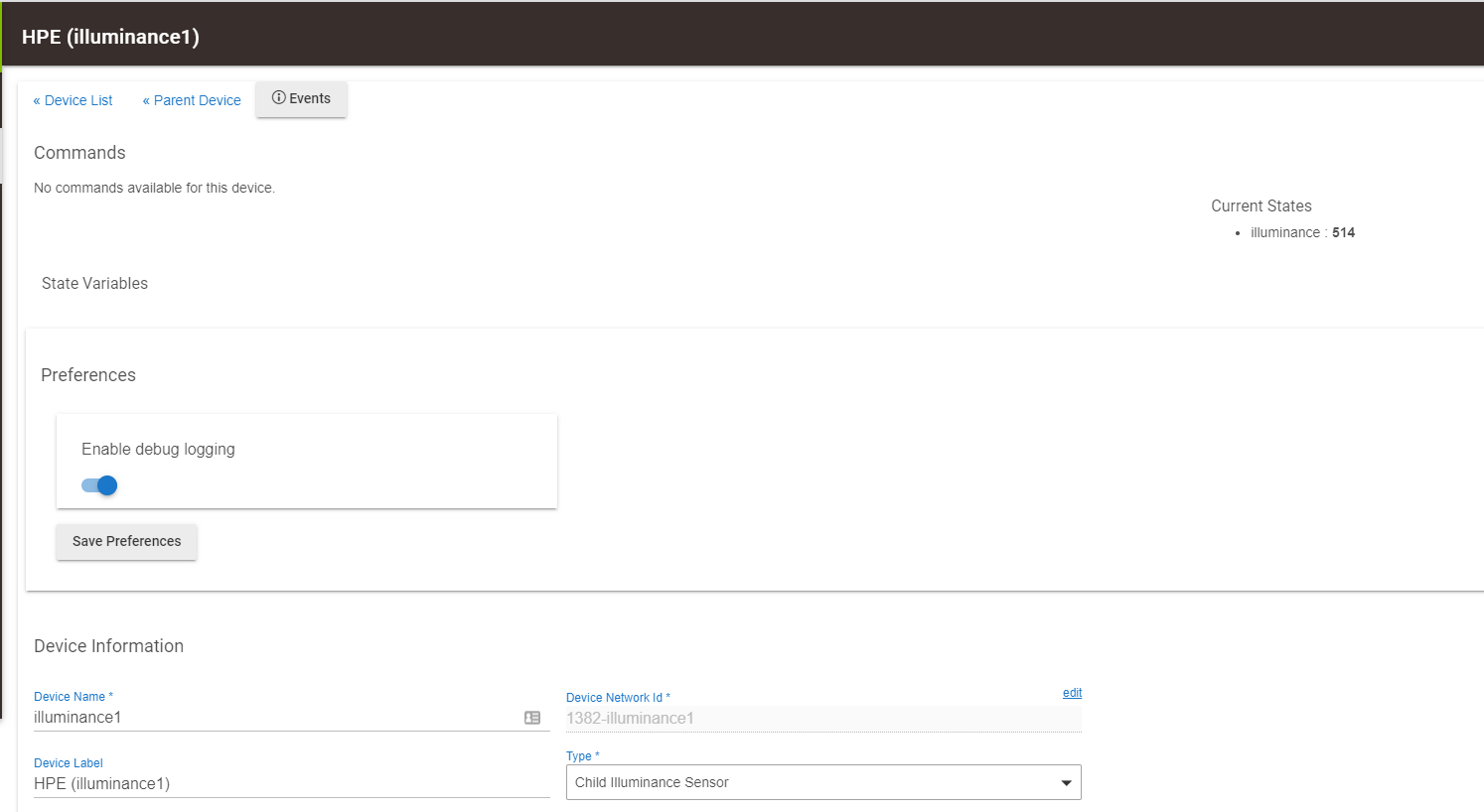
ok, so that's just what you get when you blindfold yourself and feel around in the dark hoping to touch a wall so you can feel you way to the light switch. Literally in this case. After that stupid error, the illumance1 sensor appears "magically" under the Parent device.
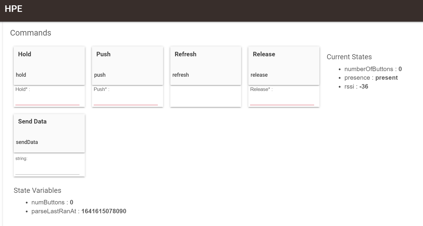
For anyone else plugging this stuff in a Hubitat, this is the desired results:
Now, one more thing. I'm interested in how this "Presence" detection works. Does it use the 'rssi' value to determine presence?
I look forward to exploring more device types down the road. I've always wanted to make my own PIR, humidity, temperature sensors!!
So many thanks to you for developing this for all of us tinker types. I'd love to learn programming at that level, but until then... "your the best!". I'd like to make some contribution to you and your son for all the hard work that went into developing this system. Please let me know. my email is s1godfrey@hotmail.com
If Hubitat receives an update from the microcontroller, then the Parent device is marked as “present”. If an update does not come within the timeout specified in the parent’s settings, the the parent is marked as “not present”, indicating a possible problem.
I appreciate the offer, however I do not accept any donations. I’ve received plenty from others' hard work, and this is my way of giving back to the community.

