With nothing connected to the analog In1 its reading 8.45v and measuring the same with a volt meter measure the AI, nothing connected to it. Only 10V power is applied to the Fibaro. Analog In2 is also reading the same 8.45v and I never hooked anything up to that one. Seems like its pulled up internally?
Does yours have a voltage reading with nothing connected to the In1 and Analog Pull-up disabled?
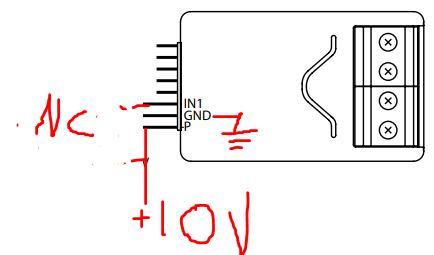
I have mined hooked up like this:
If I increase the supply voltage to >12V then the Analog reading and measure AI wire on both inputs start to exceed 10V with nothing connected so not going any higher then that. Seems like I have some issue with this unit.
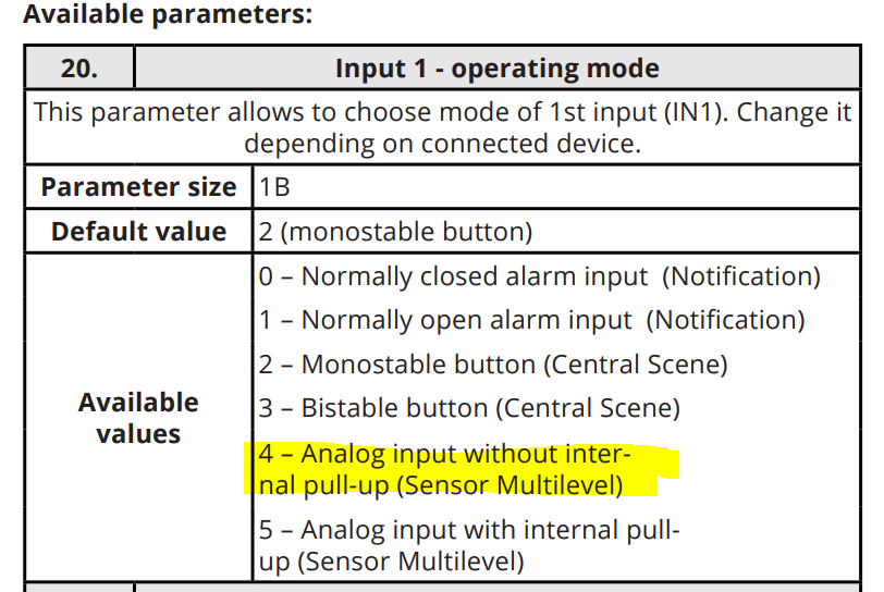
With nothing connected on IN1 configured without pull-up, you should be reading 0V and it shouldn't vary with supply voltage. So unless you entered something in the analog child device "equations" or there is something wrong with your configuration then yes something is wrong with the implant.
Maybe reset the implant to factory defaults and try again...
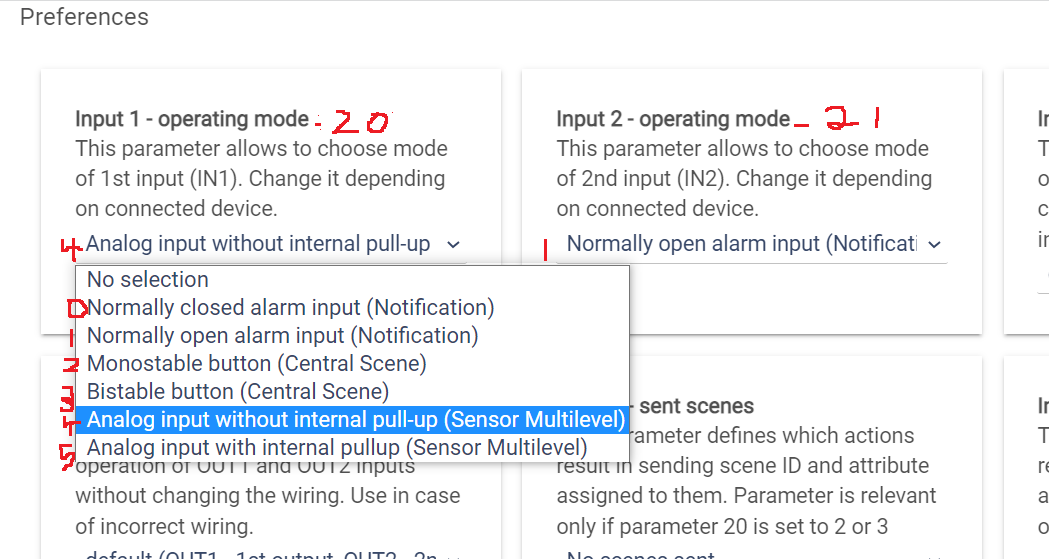
Got all the sensors working with this DH. Small potatoes but would be helpful in the driver preferences if the Parameter number and selectable value numbers were displayed so less need to look at the device docs.
I received my Z stick yesterday and got PC Controller running on an ancient Win10 laptop and was able to add the Implant with this driver as well as the Aeotec HDSS (the device that actually needed the Z stick so I could include it with no security) but now I’m realizing that all the devices I’ve been adding lately have multiple sensors in them, and I’d like to disable these individual sensors because not only are they adding to traffic on the mesh, but they are confusing Alexa because she listens to both ST and HE skills. I don’t need a motion sensor in the garage telling me what the temperature is, and when I ask Alexa the temperature of the garage, she tells me “the average temperature of the garage” based on all the temperature sensors in these devices. If I disable the device in the Alexa app, it also disables motion sensing or whatever the device is supposed to do.
On the Implant, I’m only using two DS18B20 sensors for indoor and outdoor temperature readings, and the Alexa app seems to let me disable the other child devices individually, but they still clutter the mesh; is there a way to disable the internal temperature sensor as well as the inputs and outputs?
If you don't use the inputs/outputs, I don't think any messages will be generated by those. Same goes for the internal temperature sensor, unless automatic reporting is enabled or something is polling them from outside the driver.
Removing the child devices will require changing the driver code, not simple. An easier method might be to use virtual temperature sensor devices and update them whenever the implant's temperature changes using rules.
Ok I see that. And thank you again for your work on this driver. I’m kind of getting baptized by fire with HE; I’ve owned the C7 for a couple of years (since the ST Groovy EOL announcement) but haven’t played with it at all. I suspect there are quite a few of us stragglers now scrambling to make life relatively normal once again, to appease SWMBO. I’ve adjusted parameters on all the devices in the garage that ply together in a set of Rules to control the garage heater, and the only thing left — not related to this driver — is to figure out why Alexa sees the Aeotec HDSS as a temperature sensor even though I’ve disabled temperature reporting in HE.
Looking at the values coming out of my implant right now, I see the values jump by either 0.02V or 0.03V because of noise (looking at the 3V to 5V range). This would correspond to 9 bits.
Had almost given up on ever getting a temperature input (of either type) to work when I saw your post. Thanks so much for pointing out what must have been obvious to others.
I was trying to tweak the default hubitat device handler so that I could make the local protection feature programmable (e.g controlling when the doorbell makes a noise v.s. sending a notification.
Do you know what the differences are between this and the default hubitat version?
And I saw your post and my one DS18B20 lead is kicking out a temperature reading every temp delta of 1 deg F, as chosen in the device page. Agrees with my Ecobee thermostat....I love it.
edit: Plus, even every 5 minutes, as chosen on the device page. I've been so used to Zigbee devices having a mind of their own, this is a pleasure.
A question to the other users:
How do you put it all together?
On my test setup, with one 9m lead, I soldered the wires together and have a cable tie holding it all together.
For the actual install involving readings around 2 boilers, I might even max out the six leads, if it'll work.
I figure still solder the wires together and secure it with a cable tie, and maybe coat the connections with some sort of insulating 'goop'-maybe the hardware store has something.
Put it all into a plastic box of some sort-maybe a plastic switch box with a blank cover over it, also from the hardware store.
What are best, or even not so bad, practices for this tiny device with its tiny wires?
I agree. Making a note in each parameter box as to what parameter number it is would be very helpful.
Otherwise, this driver is fantastic and makes the implant a pleasure to use! So versitile!
My only pain is that to add/remove a temp sensor, the device must be excluded and re-included, which breaks any rules that use the SI.
Also, I tried changing the driver to an existing device, that was already in use, to this new driver, and the only way to "update" to the new driver was to re-install, which would "break" any rules....
PAINFUL!
Is there a way to change the driver on an existing device without having to repair the broken rules?
Another note....
I have two of the smart implants running in HE.
One is the HE driver and the other is this community driver, which is ALOT nicer to use.
I would like to change the driver of the first SI to the community driver, but not loose the rules that uses the SI.
Is it possible to change drivers without having to re-define all of my rules, or do I have to "start over" ?
No, to go from one driver to the other, the child devices needs to be first erased (this is when the rules are broken) and then re-created by the new driver.
I am not sure I follow... The switches have an on/off state updated when they are operated. If you are trying to have an input directly controlling the switch then you can set the parameter "Local Device Protection" to 0 and use either the normally open or close alarm mode for the input.
I am not very familiar with the bistable button mode (central scene). The warning message you see just means I have not written any code to handle that message.