The sensor common should implicitly be connected to the Fibaro ground since you use the same power source for both. The ground wire of the power source goes to both device's common?
Just configure the input "with internal pull-up" instead of without and test again, that will do the same thing.
I don't think a floating input would result in the implant to report voltage higher than 10V. It should never happen as far as I am concerned since the spec says it is a 0-10V ADC. Looks like something is wrong with the implant to be honest. Out the top of my head, some things to try:
-When testing with the input "with internal pull-up", enable the logs and post everything that shows in the log for the "save preferences" and "configure" commands
-Factory reset the implant
-Use a lower and stable voltage (e.g. 12V) for the implant. Connect both voltage sources grounds together.
-What "firmware" value is reported in the state variables for the parent device?
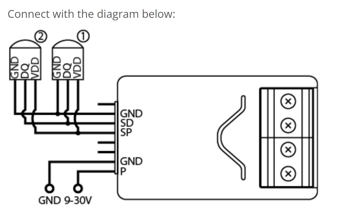
If I want to connect three DS18B20 sensors to the implant, would this be the correct wiring way of wiring the sensors to the implant before I join it to the Hub?
Red wire of the sensor to SP
Yellow wire of the sensor to SD
Black to Ground.
I'm I correct that no resistors are required?
Despite spending some time reading this discussion, I'm confused as to how the driver should be configured. Do I use the Child Digital Input or Temperature Sensor as child device?
Your wiring looks good, no resistor required. You configure the driver by setting "External sensor type" to DS18B20 and "number of external DS18B20" to 3 in your case. Then press "save preferences" and "configure", can take up to a minute.
The driver should create 3 external temperature child devices.
I had a really long reply written with the results of several actions, none of which changed the outcome. Then I decided to wipe the slate clean and try it again, this time checking things along the way. I did a factory reset on the Smart Implant, then did a soft reset on the HE. Next, I reinstalled the SI using the driver shipped with HE.
After the SI was installed with the HE driver, I changed IN1 to analog input without internal pull-up, which is what I always thought it should be. Without connecting the pressure sensor, I checked the voltage across IN1. It was a few millivolts. Good so far. Next, I connected the sensor to IN1 and powered it up. Voltage across IN1 was still a few millivolts. Again, good. Lastly, I blew into the high pressure port hose while continuing to check the voltage across IN1. As I blew harder, the voltage rose. The voltage got to 10.04V and stopped increasing, so it looks like the pressure sensor will never exceed 10V, even if the pressure goes over 1 wci. All the above voltage checks were done with a volt meter, not by refreshing/viewing the device screen.
The only problem I see so far is that the device screen for IN1 always shows 0V, even when I'm blowing in the tube and the voltage is increasing (according to the volt meter).
I'm not in any way suggesting that there is a problem with the custom driver. I'm sure I screwed something up along the way, and the only way to fix it was to start over. Now that volt meter checks show that it is working as expected (I think), I will soon reinstall the custom driver and see what happens. Should know something in a few days. I guess the downside is that we've spent so much time trying to figure this out, when it turns out it was probably something I did wrong.
Yes, this is what you should use with your sensor. However for testing, you can configure the implant WITH an internal pull-up. In that case, without anything connected you should get 10V readings. If you then short the analog input to ground you should get 0V readings. That will tell you if the implant works as expected by itself.
I did a complete restart again (soft reset on HE, factory reset on SI, excluded SI, reinstalled custom driver, etc.). I didn't test with the HE-supplied driver. With the custom driver, the voltage goes up as I blow on the tube, up to a maximum on 10.14V. Here's one of the log messages...
dev:12022-09-20 01:11:39.589 pm debug{Sensor @ endpoint 3 has value 7.66 - ep=3 Fibaro Smart Implant 1 - Analog Input 1 SensorMultilevelReport(precision:2, scale:0, sensorType:15, sensorValue:[2, 254], size:2, scaledSensorValue:7.66) }
Thanks for your assitance. Received the DS18B20's today and within 20 minutes all three probes were reporting fridge/freezer temperatures. The implant is a fantastic device (and probably underestimated), especially with your driver.
Thanks for your time and effort in this regard.
Bought an SI a couple of years ago, but only started testing it a couple weeks ago. I have a fair bit of experience with Arduino & Tasmota, but love the size and simplicity of the SI. Recording my experience here in case it can help someone in the future.
I am using both inputs (1 x Digital for 2 x wired PIRs plus 1 x Analog reading a 12v battery) and both outputs feeding a 5v relay module. Did the proto-typing for this and with only a slight bit of trial & error - everything was up and running! No Arduino programming and no Tasmota flashing, so good start...
But then I started with the DS18B20's. I need the implant to read four sensors which is well within it's capabilities. I know that all the sensors work because I currently read them through Tasmota and an ESP32. And again I have a fair bit of experience with DS18B20s and so have tried everything I can think of, but can not get them to work consistently. Here are the iterations I have been thru:
Running 1, 2 & 3 DS18B20s at 3.3v powered from SI with no pull-up resistor.
Running 1, 2 & 3 DS18B20s at 3.3v powered from SI with a 1k pull-up resistor.
Running 1, 2 & 3 DS18B20s at 3.3v powered from a separate power supply with 1k pull-up resistor.
Running 1, 2 & 3 DS18B20s at 5v powered from a separate power supply with 4k7 pull-up resistor.
The DS18B20s will show up with the native HE driver, but within minutes one of them will start reporting incorrectly and within 15 minutes the other units will be under-reading by about 10°C
With the custom driver, the DS18B20s always show as 'Unknown'
Just to re-iterate - there is nothing wrong with the DS18B20s - quality, cable length etc. They have worked fine with 3 different MCUs over a period nearly two years. Every time after I do some testing with the implant, I reconnect them to their current ESP32 MCU and they report with no issues.
Seems from my reading here and on other sites that this is not an uncommon problem. I have wasted so much time prototyping & it is disappointing that such a good MCU can have such a basic flaw/inconsistency. Recording it here to hopefully help someone else not waste too much time trying to get it to work in the future.
BTW @christi999 - thank you so much for your work on this driver, it is super. It runs much quicker and cleaner for my input/output setup with no apparent bugs - compared to sluggish and buggy using the native HE driver.
Is it possible to use the Implant to report the input voltage of the power source? I'm using an implant to control my gate motor (and serve as a contact sensor at the same time.) The implant is powered by the gate motor's backup battery and being able to check the input voltage, should give an indication of the condition of the backup battery.
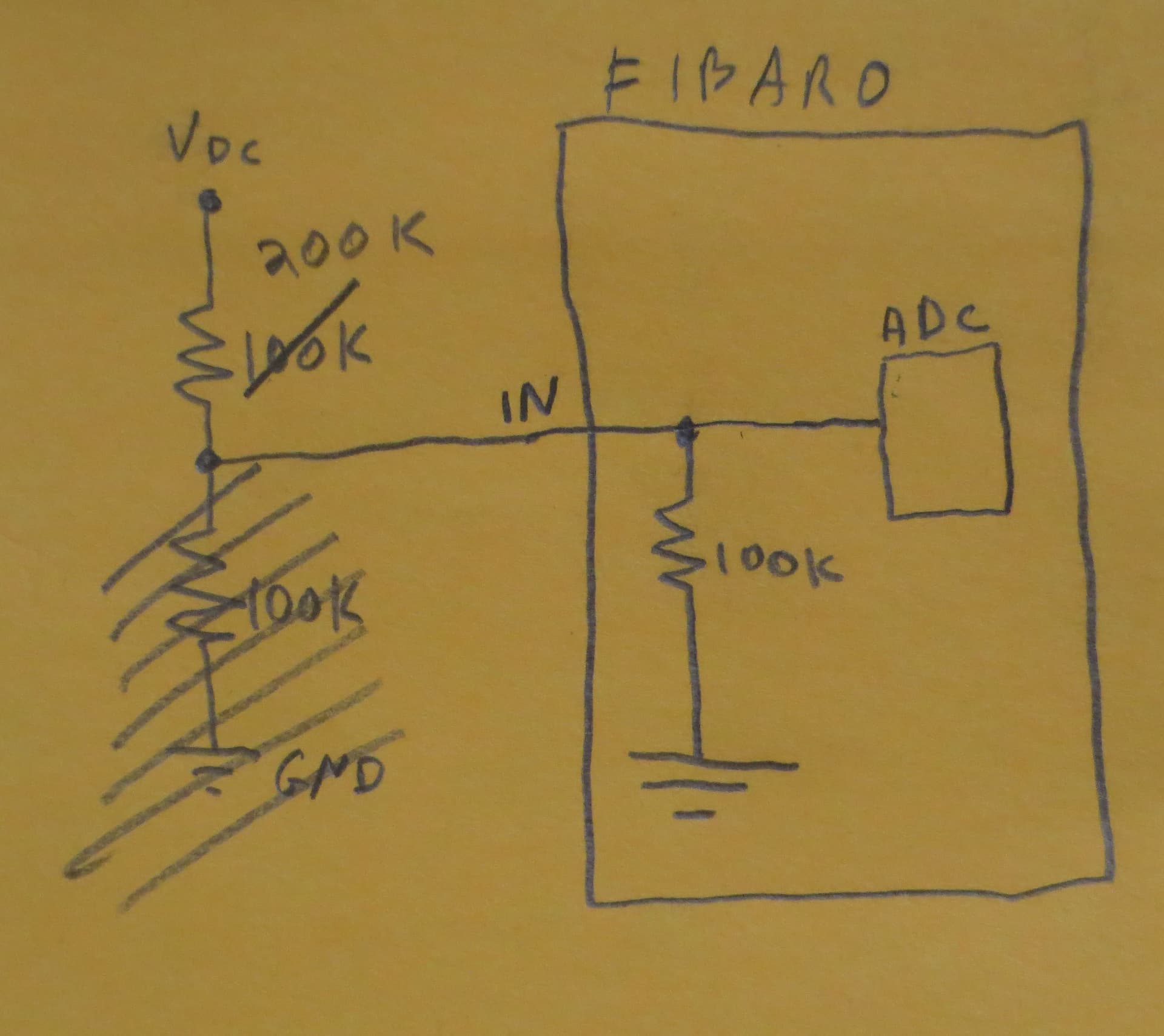
Assuming you have one of the two input free, you can use a voltage divider (two resistors) between ground and your voltage source. Connect the middle of the two resistors to the free input (configured as an analog input without pull-up). If I remember correctly, the input impedance is around a 100kohms.Let me know if you need more details, values...
Thanks a million. Yes, I only used one output (for the motor relay) and one digital input (for the contact sensor)
I've never done something like this (i.e. working with resistors), but I'm going to try when a get the time. How does one measure the "input impedance" and does that determine what resistors are to be used?
The voltage read by the implant will be 1/3 of the Vdc voltage source so you just need to multiply the values returned by 3, which can be done directly in the analog input child device.
The value 3 is approximate and depends on the resistor values, if you need more precision, you could measure the source voltage with a multimeter and divide by the value returned by the implant. In my case I got 2.91...
Thanks for your reply. I'll hopefully be able to test it this weekend. Waiting for a replacement transformer for the gate motor backup battery, which I blew up while fitting the Implant. Long story and too embarrassing to repeat.
Im running my Fibaro on a voltage source that can vary from 20 to 29Vdc. Im trying to set up the analog in1 to measure that voltage. I set it up like your picture above with a voltage divider, just the 200K resistor. Assuming that 100K resistor is internal. Set up the driver "With Out internal pullup". Source adjusted to 10V for safety reason to not overload the AI just incase, I measure and read 8.53v. You sure that internal 100K is not a 1M resistor? Should read more like 3.3V, not 8.53v
Mine was about 100K, I don't exclude that they might have changed the design... There will be some variations on that value from implant to implant and also on your 200K resistor. The implant has a minimum 9V +/- 10% minimum supply so at 10V you might be a bit close to the minimum value, not too sure how the implant reacts to that.
In any case, the divider is there mainly to bring the voltage to a safe and measurable level. The actual multiplier value should be measured with a voltmeter, irrespective of the resistors used.