[RELEASE] Fibaro Smart Implant FGBS-222

I've always found multiple ds18b20 s problematic, with odd issues.

Possibly for the reasons you guessed.

Always found it better to use one per module, although I've currently got 2 modules with 2 sensors each.

But I sacked off fibaro and went with konnected / nodemcu for cost.

This has been up and running for quite some time.

I have two smart implants with 6 x DS18B20 on each work pretty well, get the occasional error on a DS18B20 where it doesn't read properly but thats is resolved with a refresh.

You have to connect all the DS18B20 first then include the smart implant.

1 Like

I have a pressure sensor that I want to use to monitor the backpressure in my clothes dryer duct so I can see when dryer lint buildup is reducing the dryer exhaust. The sensor outputs 0-10Vdc or 4-20mA. Can I wire the sensor output to the Fibaro Implant's analog inputs, then have HE poll the Implant every few seconds/minutes (when the dryer is running) to get backpressure readings on the HE dashboard? And if the backpressure reaches a specified level, trigger an alarm? Does the Implant driver support this kind of stuff?

If you can't tell by the questions, I'm just getting started with HE and z wave devices. I do have experience with older smart home technologies. Thanks.

What you describe should work perfectly fine with a sensor voltage of 0-10Vdc and the right pressure range. Polling the driver, display and triggering an alarm will require you to write some simple rules or code outside of the driver.

I have a Smart Implant on order so I can bench test it and become familiar with it. In the meantime...

I would like to poll the device frequently when the dryer is running. Given that I don't have any idea how many devices I will eventually have defined to HE, what is a reasonable poll frequency? Seconds? Minutes? I expect there won't be very many devices that are polled on a frequent basis, but who really knows.

The backpressure in a dryer exhaust duct is supposed to be very low. One manufacturer said it should be below .6wci, which is only .02psi. The pressure gauge senses 0-1wci, so voltage should be between 0 and 6V, unless the duct gets really clogged.

From the doc, it looks like the Implant could maybe also be used to sense dryer on/off by using it to report that the voltage increased/decreased by a specified amount (parameters 63 and 64). I have no idea what a very clean duct (i.e., new) will report since the house is still under construction. My guess is that with such low backpressure, the voltage reading may fluctuate quite a bit while the dryer is running. I guess rules could be used to ignore reported changes, except the first one (when dryer starts), and when it goes back to zero (when dryer stops). If my assumptions are correct, is the Implant a good way to detect when the dryer starts/stops? I'm trying to stay away from anything that requires me to "open up" the dryer or mess with 120V wiring. It is a gas dryer.

Polling every minutes or couple of minutes is probably more than enough.

I think detecting ON/OFF using the pressure might work with some tweaking. There may be cases where it fails e.g. pressure change due to wind or blocked conduit (pressure too low to trigger ON/OFF trigger point). I guess playing with it will show you if it is good enough. Using rules to implement this approach might be tedious and I would personally prefer to write a dedicated app.

Ideally to detect ON/OFF, the other input of the implant could be used in alarm mode with an external contact triggered by ??? (voltage, current, light, temperature or pressure detector...). ON/OFF could also be detected using a smart outlet that reports power consumption.

I'm running on HE platform version 2.3.2.141, so I'm current. I'm trying to get familiar with this environment, so all I've done is "bench test" an outlet and a few smart bulbs.

My Smart Implant arrived today, so I figured I would add it to my HE and "look around". Like I did for the other few devices I have added, I tried to add it by brand. The only device on the Fibaro list that looks close is the "multisensor". I tried including the Implant as a multisensor several times, but it never found it.

That made me think that I have to add a custom driver for it, so I tried to download and install the custom driver at the github link at the top of this thread. I used that URL as the import URL and clicked "Import". Nothing happened. No messages. No code put in the editor. I went back to the github page, clicked on the "...smart.implant.groovy" file to bring up its source code, copied that URL into the import URL, and clicked "Import". Again, nothing happened. No messages. No code in the editor.

First question... is the HE provided Fibaro multisensor driver I first tried to use the correct one? If it is, any idea why I can't add the Implant using that driver? If that isn't the correct one...

Second question (if I need to install a custom driver)... how do I import the driver I should use, i.e., what did I do wrong above?

Third question... again regarding installing custom drivers. The second line of the readme file at the github site says "-Install the 6 files as 6 drivers. Use the main driver file "...smart implant" for the device "type" of the device. This main driver will take care of using the other drivers as required (it will create child devices automatically)." I use github on a regular basis (I'm a software developer by profession), but I don't know exactly what that is trying to tell me. Explanation please.

Thanks,
Ira

  1. I've never added a device to HE using the device selector. Z-wave devices have a fingerprint that is sent during inclusion. The HE attempts to match the fingerprint to the correct driver, but it's not always correct.

With that said, I have no clue if that driver will work for this device, as I don't have one. Just wanted to provide the above detail.

  1. You were close. Once you select to device driver in GitHub, there's an option to view the raw code. You want to click that and then use that URL to import into HE.

  1. It looks like this driver uses a parent/child setup. So each of those has it's own driver. Once you have them all loaded, you'll go to the main device page, go to the device type, select the implant device, then click save. If this is like most, that will automatically create child devices for the different functions.

That did it. I saw the mention of "raw text" in the doc, but I didn't have a clue what it was talking about and didn't see the "Raw" button. I figured if I could see the actual code on github, that was good enough. After clicking on "Raw" and using the resulting URL. I was able to import it and save it.

I did try adding the Implant manually as a z-wave device (instead of by brand), but that timed out, too.

Hopefully @christi999 will see this and let me know which driver I should be using.

Thanks,
Ira

Looks like maybe I need to read up on virtual devices. I deleted the Implant driver from the custom drivers list. Next, I did "Add Device" and chose "Virtual". The "type" dropdown had a Smart Implant driver in the list. Maybe this is the one I should use, but I need to understand virtual devices first.

Sometimes I make it so hard on myself. I just stumbled across z-wave SmartStart. Took less than one minute to add the Implant and get it connected. It now shows up in my device list. No need to get any custom driver from what I can tell.

You can use the built-in driver for a start. It doesn't expose all the functionality of the implant so at some point you might want to switch to my driver.

For installation, you can do what you describe above, i.e. install the 6 drivers manually by either copying the code to each driver file or using a "raw" link. An easier way is to first install the "Hubitat Package Manager" and install the driver using that app.

If you need to switch driver, follow this procedure:

  • Choose the implant parent in "devices"
  • Switch to my device driver (go to device information section, in "type" scroll to the end of the list in the "User" section and select my driver)
  • Save Device
  • Save preferences
  • Press Reinstall, selecting "yes"
  • Change configurations as you like
  • Save preferences, again
  • Press configure
  • Wait 1 minute for configuration
  • Done

I installed HPM and used it to install your driver, as you suggested. Everything went pretty smooth. I'm now using your driver, and the features I bench tested are working correctly.

Now I need to wait for the pressure sensor to be delivered.

Thanks for all the help everyone. I will report back when I get end-to-end bench test results. Unfortunately, this will be used in a home that is still under construction, so the real world test is probably six months away.

1 Like

I think when you get the temperature sensor you may have to re-add the device again. I believe the temperature sensor needs to be connected when added to Z-Wave.

I have the pressure sensor now. Documentation for it is here...

https://www.neptronic.com/controls/pdf/SPD070-161031-ESA.pdf

I set the pressure sensor DIP switch to "0-10Vdc". I'm using a 24Vdc transformer to test it. I connected the transformer to terminal 1 (common) and terminal 2 (24Vdc input). I put a voltage meter across terminal 1 (common) and terminal 3 (Vdc output), then blew (softly) into the high side hose (low side is open to atmosphere). Volts did increase, then decreased when I stopped blowing. So it looks like the pressure sensor works.

Looking at the Fibaro doc, it looks like there are two ways to connect a 0-10V sensor. I want to make sure I do the right thing, so let me know if this is correct.

I think I need to use the diagram shown in topic "4.6: Connection with 3-wire 0-10V sensor" on page 4. Based on the diagram, the pressure sensor and the smart implant will be powered by the same 24Vdc transformer (do they have to?). The transformer will be connected to the sensor the same way I have it now. The transformer will also be connected to the Smart Implant blue wire (ground) and red wire (power). The Smart Implant IN1 (yellow) wire connects to the pressure sensor terminal 3 (Vdc output). Is this correct?

Thanks,
Ira

No, but their ground/common will be connected together.

Everything looks good to me.

I have it set up as previously described, using one 24Vdc transformer for both devices. Smart Implant inputs 1 and 2 are set to "Analog input without internal pull-up". Everything else is using default settings. The sensor output is connected to the Smart Implant input 1 wire (yellow).

When I plug everything in, the current state voltage and raw voltage hover around 21V +/- about .1V. I checked the voltage across the pressure sensor output and common, and it was a little less. Blowing into the high pressure side didn't change the voltage.

I was expecting to see 0-10V across the sensor output, and the same on the Smart Implant input 1 device screen, Since I didn't, I disconnected the sensor output and checked the output voltage again, and it was almost zero. Voltage went up on the output when I blew into the high side hose.

Am I seeing the expected results, but I'm interpreting them wrong, or should the Input 1 screen show 0-10V, depending on the hose pressure, instead of a fairly constant 21V?

the "raw voltage" state variable in the child device should never be above approx. 10V so something is definitely not right based on your description. I would suggest enabling debug logging in the parent device (and then save preferences) and post the logs as you are executing the "refresh" command in the analog child device.

I would expect the sensor output to have high voltage (e.g. 21V) if it is used in current mode and the output is open (no resistance or 100kohms for the implant), i.e. output 4 instead of 3...

I assume your transformer has enough power to supply both units?

Made some edits in my previous post...

Good call on the transformer. It was only 1.5 amps. Unfortunately, that's not the problem. I switched it to a 24Vdc 4A transformer, and nothing changed. The interesting thing is that it shows the same IN1 voltage whether or not the sensor is connected to IN1. Also, the IN2 input shows about the same 20V, even though nothing has ever been attached to the IN2 input wire.

I found a thread from March 1 on the Fibaro forum where someone was using a 0-10V temp sensor, and he was getting 20V on IN1 and IN2 even though nothing was connected. The only reply he got was "that's probably just a floating voltage when you have nothing connected. If you want to double check, connect a 1M ohm resistor between ground and the input and measure the green wire voltage again. It should be close to zero". Unfortunately, the OP never replied after that, and I don't have any idea what the respondent was alluding to.

I emailed Fibaro support to see what they have to say.

I don't know if it matters, but I did not connect the pressure sensor common to the Fibaro ground. I assumed that sense they were both using the same transformer, the common and ground would be connected that way. Could that be the problem?

Here's the log...

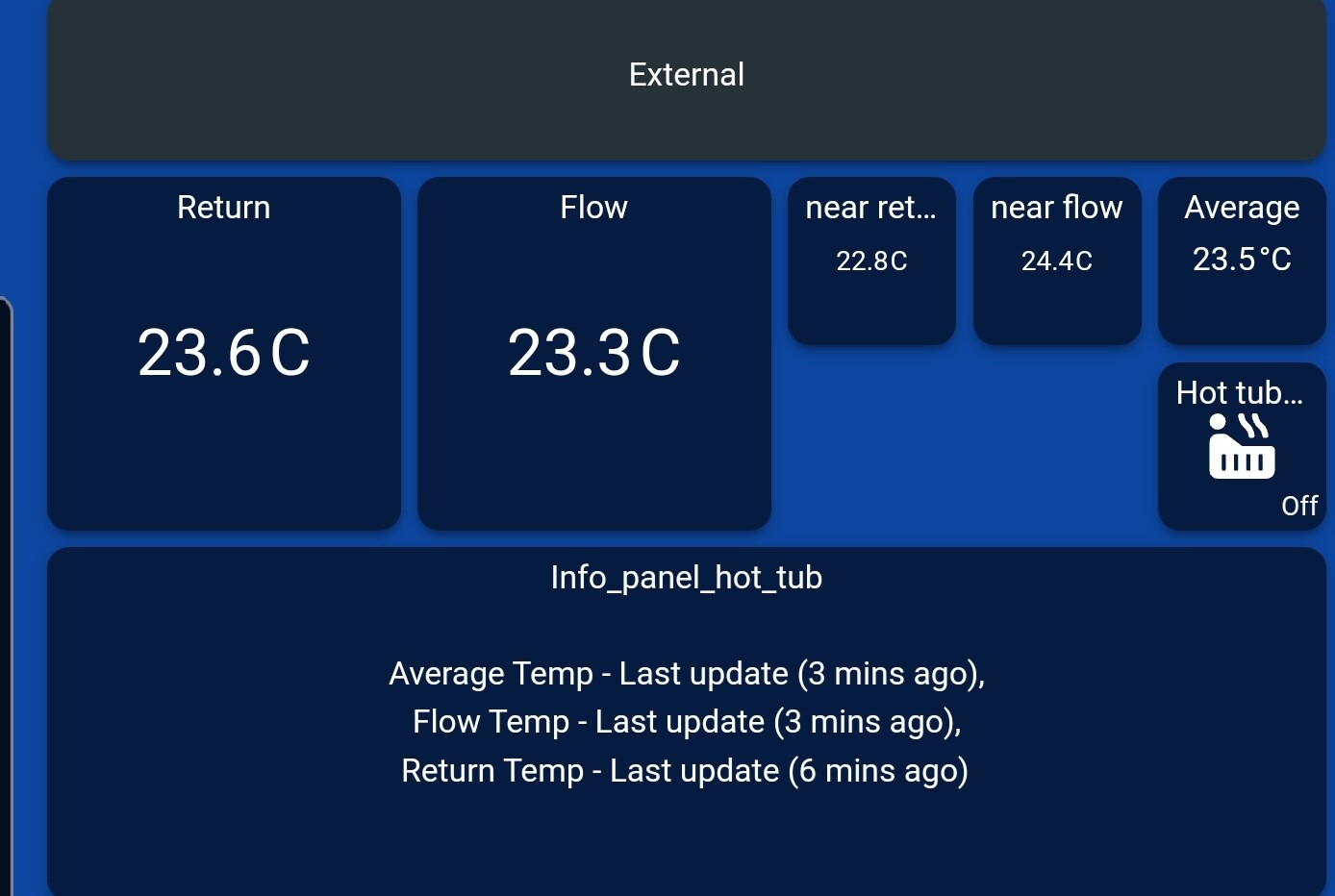
dev:332022-09-18 10:11:54.524 pm debug{Sensor @ endpoint 4 has value 21.35 - ep=4 Fibaro Smart Implant - Analog Input 2 SensorMultilevelReport(precision:2, scale:0, sensorType:15, sensorValue:[8, 87], size:2, scaledSensorValue:21.35) }

dev:332022-09-18 10:11:54.428 pm debug{S2_AUTHENTICATED}

dev:332022-09-18 10:11:54.422 pm debug{childRefresh, ep=4}

dev:332022-09-18 10:11:41.222 pm debug{Sensor @ endpoint 7 has value 31.2 - ep=7 Fibaro Smart Implant - Internal Temperature SensorMultilevelReport(precision:1, scale:0, sensorType:1, sensorValue:[1, 56], size:2, scaledSensorValue:31.2) }

dev:332022-09-18 10:11:37.976 pm debug{Sensor @ endpoint 3 has value 21.37 - ep=3 Fibaro Smart Implant - Analog Input 1 SensorMultilevelReport(precision:2, scale:0, sensorType:15, sensorValue:[8, 89], size:2, scaledSensorValue:21.37) }

dev:332022-09-18 10:11:37.715 pm debug{S2_AUTHENTICATED}

dev:332022-09-18 10:11:37.628 pm debug{childRefresh, ep=3}

dev:332022-09-18 10:10:46.561 pm debug{Sensor @ endpoint 7 has value 30.6 - ep=7 Fibaro Smart Implant - Internal Temperature SensorMultilevelReport(precision:1, scale:0, sensorType:1, sensorValue:[1, 50], size:2, scaledSensorValue:30.6) }

dev:332022-09-18 10:10:08.028 pm debug{Sensor @ endpoint 7 has value 30.0 - ep=7 Fibaro Smart Implant - Internal Temperature SensorMultilevelReport(precision:1, scale:0, sensorType:1, sensorValue:[1, 44], size:2, scaledSensorValue:30.0) }

dev:332022-09-18 10:10:07.503 pm debug{SwitchBinaryReport - ep=6 Fibaro Smart Implant - Output 2 SwitchBinaryReport(value:0, targetValue:0, duration:0) }

dev:332022-09-18 10:10:06.985 pm debug{SwitchBinaryReport - ep=5 Fibaro Smart Implant - Output 1 SwitchBinaryReport(value:0, targetValue:0, duration:0) }