Prototype contact sensor for sliding patio door LOCK

EDIT #2: See post Prototype contact sensor for sliding patio door LOCK - #11 by John_Land for my latest (and hopefully LAST) sensor based on a modified magnetic contact sensor (that doesn't use magnets for activation, but instead used an external switch).

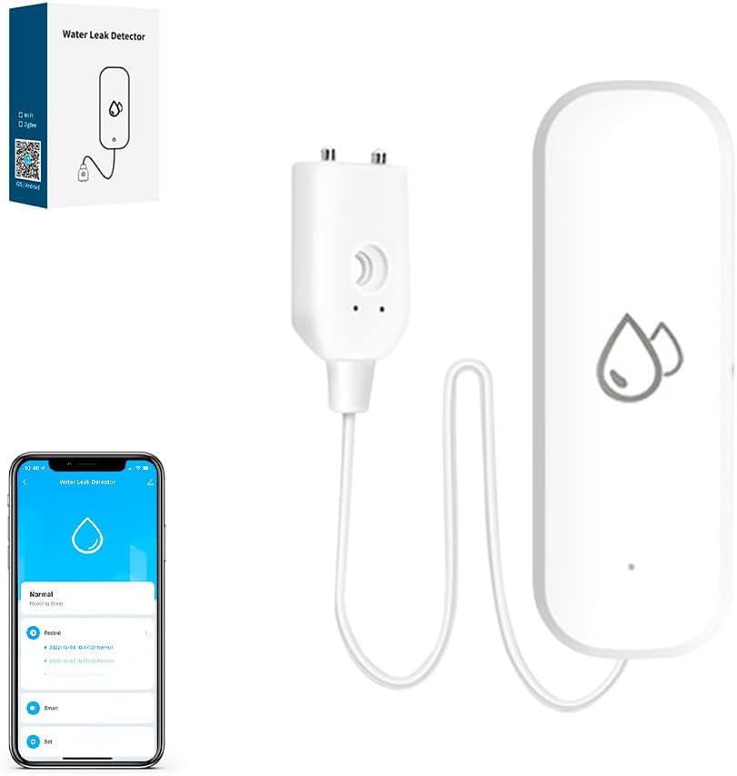
EDIT: this first post was about a prototype magnetic contact sensor for a sliding patio door LOCK. See post Prototype contact sensor for sliding patio door LOCK - #8 by John_Land below for my 2nd (improved) prototype based on a water leak sensor.

Below are pictures of a prototype of a patio sliding door contact sensor apparatus for detecting a locked-unlocked condition (this is different from determining door open or closed). This was inspired by another user's solution for a Pella slider that allows a different approach.

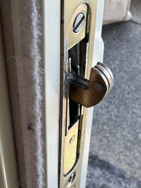
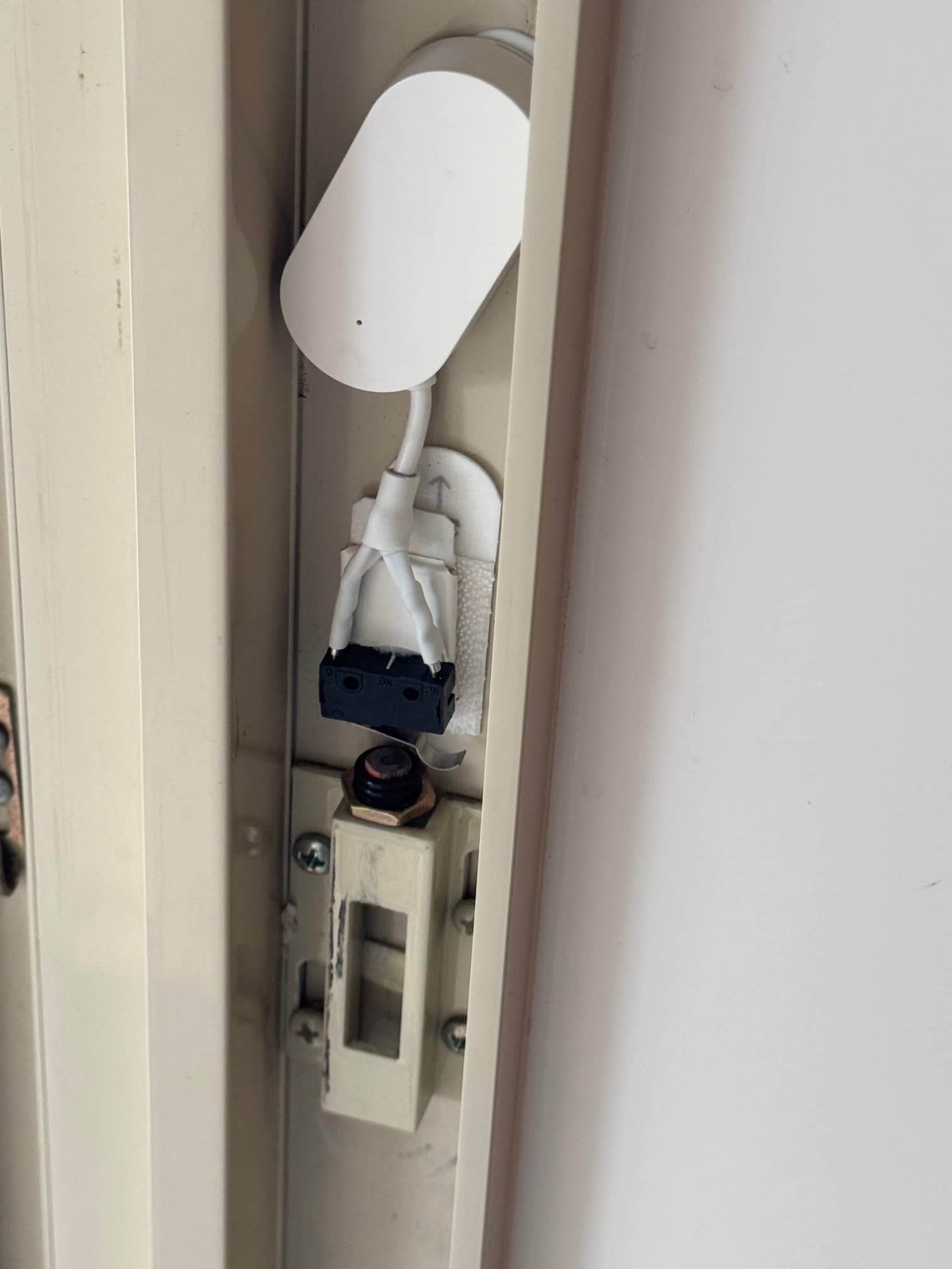
The first picture shows the locking mechanism of the slider door in the "locked position". In the unlocked position, the "hook" drops down and retracts into the door.

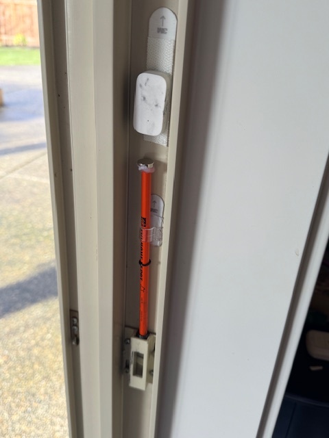
The second picture shows a standard pencil with a magnet hot-glued to the non-eraser end, while the eraser end is placed within the raised latch channel that the "hook" engages when locked. O-rings are used to limit travel in both directions, and a plastic cable/wire guide is used to hold and guide the pencil.

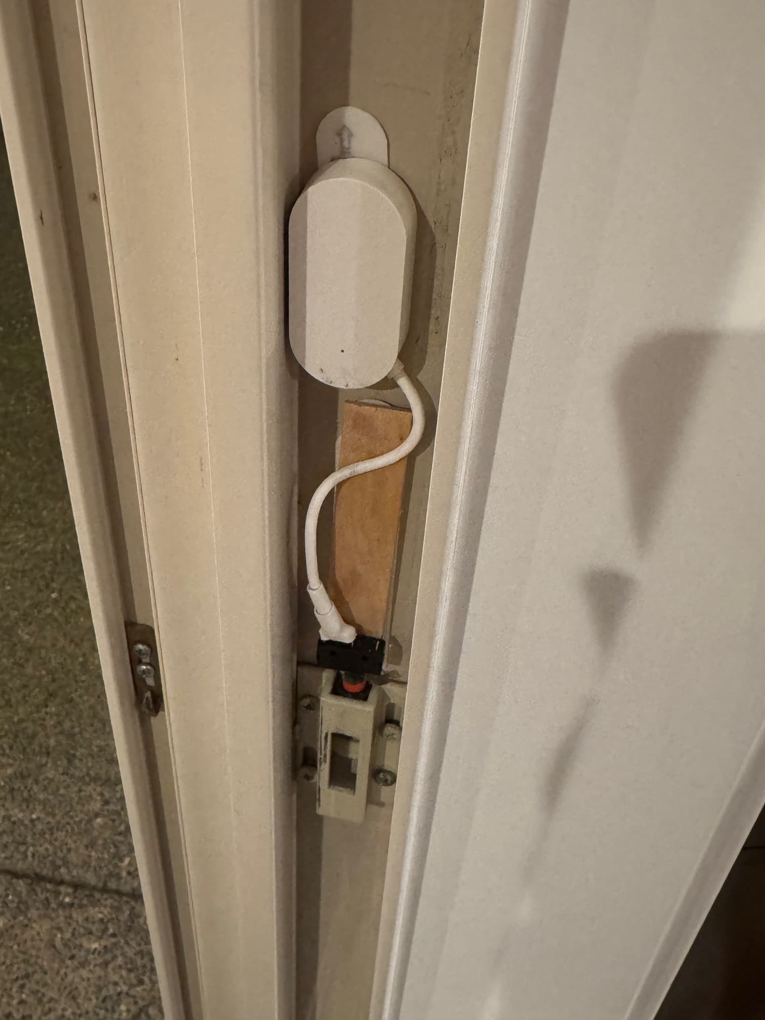
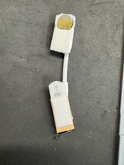
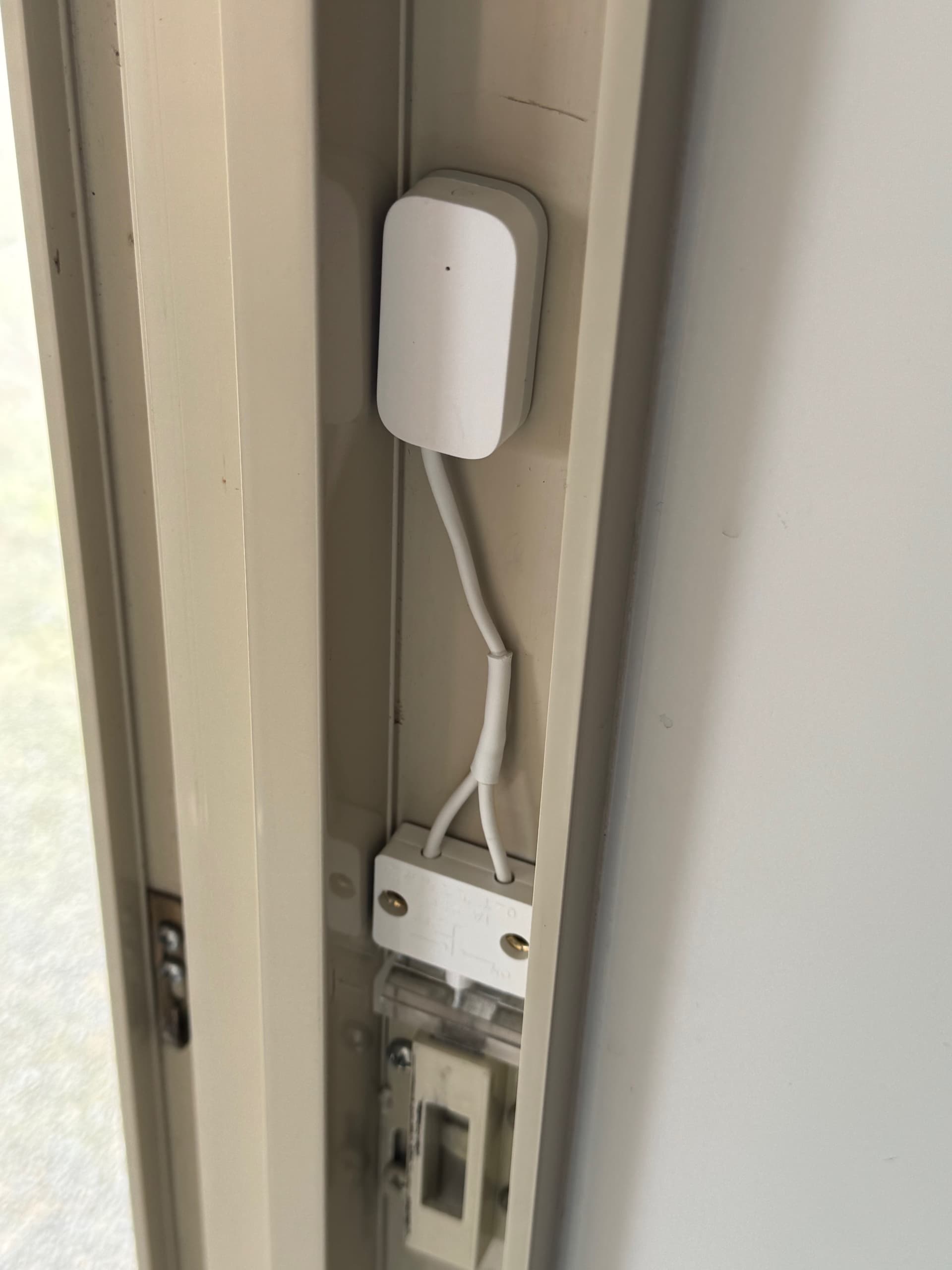
The magnetic sensor is an Aqara Zigbee unit with a bit of loop material glued to the back, which engages a 3M hook strip adhered to the door frame. Using hook-and-loop materials allows resettable positioning of the Aqara unit. The Aqara sensor is the smallest and thinnest magnetic contact sensor that I've come across and JUST fits depth-wise within the channel of the slider door frame.

The upper O-ring prevents the magnet from pulling too close to the sensor (and sticking to it) by hitting the bottom edge of the guide. The weight of the pencil helps to pull the magnet away from the sensor when the door is unlocked (so no spring needed).

This works tolerably well, but the spacing of magnet and sensor is touchy. There appears to be a bit of hysteresis in the spacing engagement, with the magnet having to move further away from the sensor to register open then the magnet had to move to register closed (e.g., 1/8" closer from rest to be CLOSED, but 1/4" away from the CLOSED position to be OPEN). The door "hook" provides just about 1/4" of upward travel so the spacing can be set to work.

The Aqara sensor sits in an aluminum channel and the face of the slider door frame is steel, so the signal is weak. I have 2 Zigbee in-wall switches just inches from the sensor, so I do get a signal.

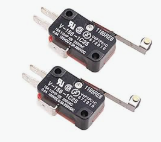
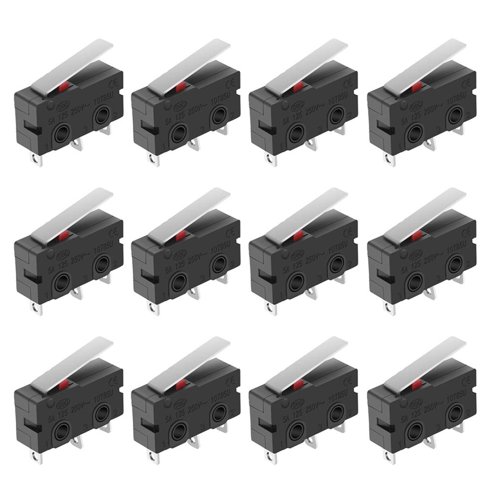
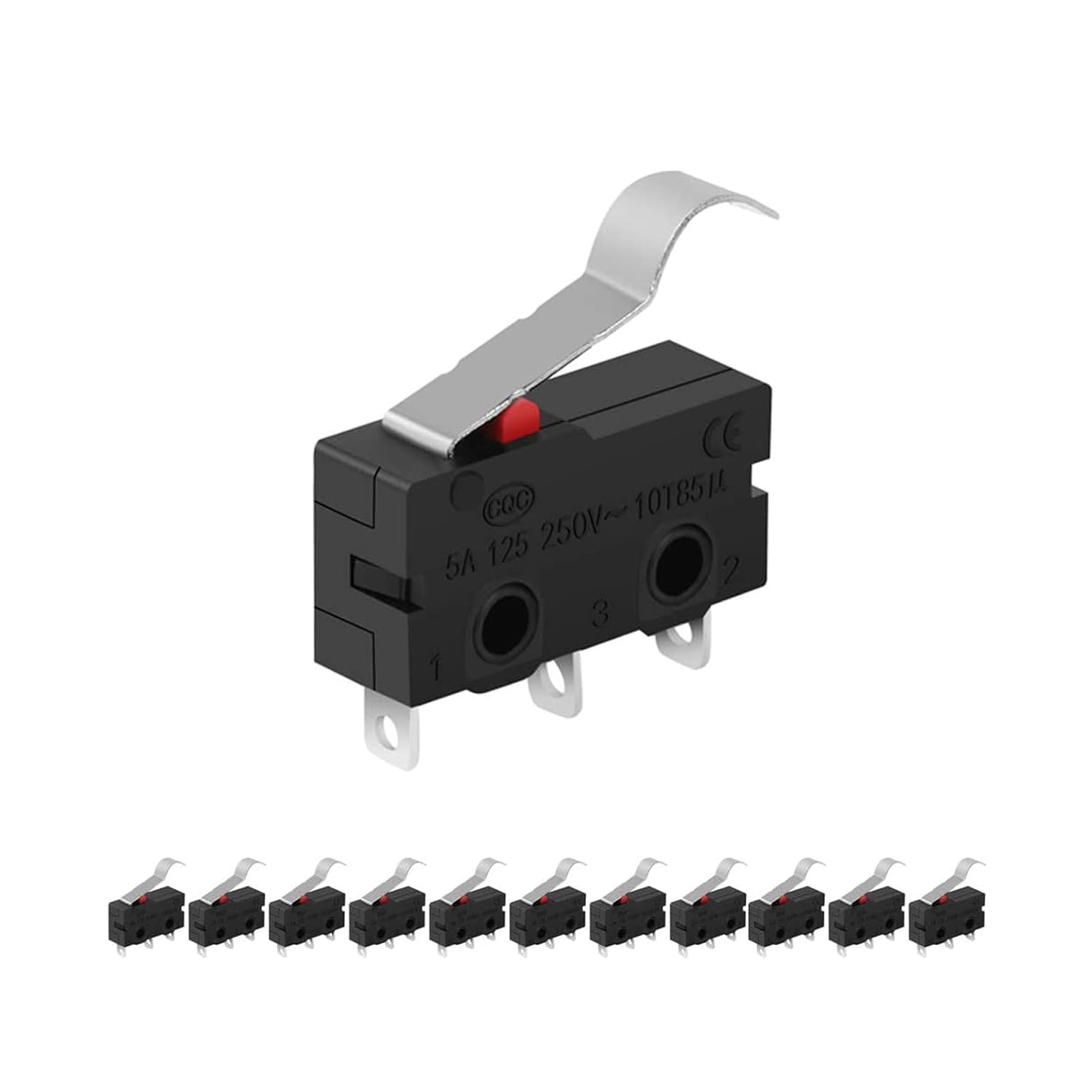
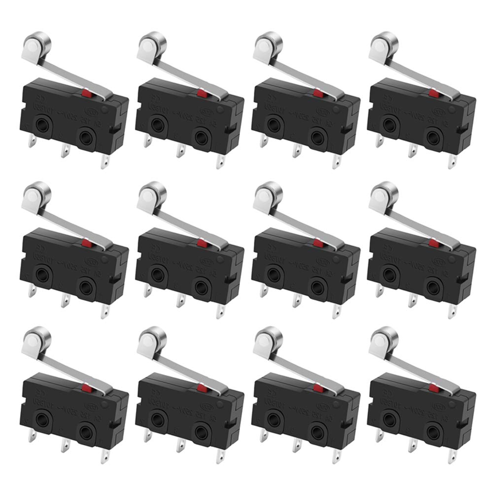
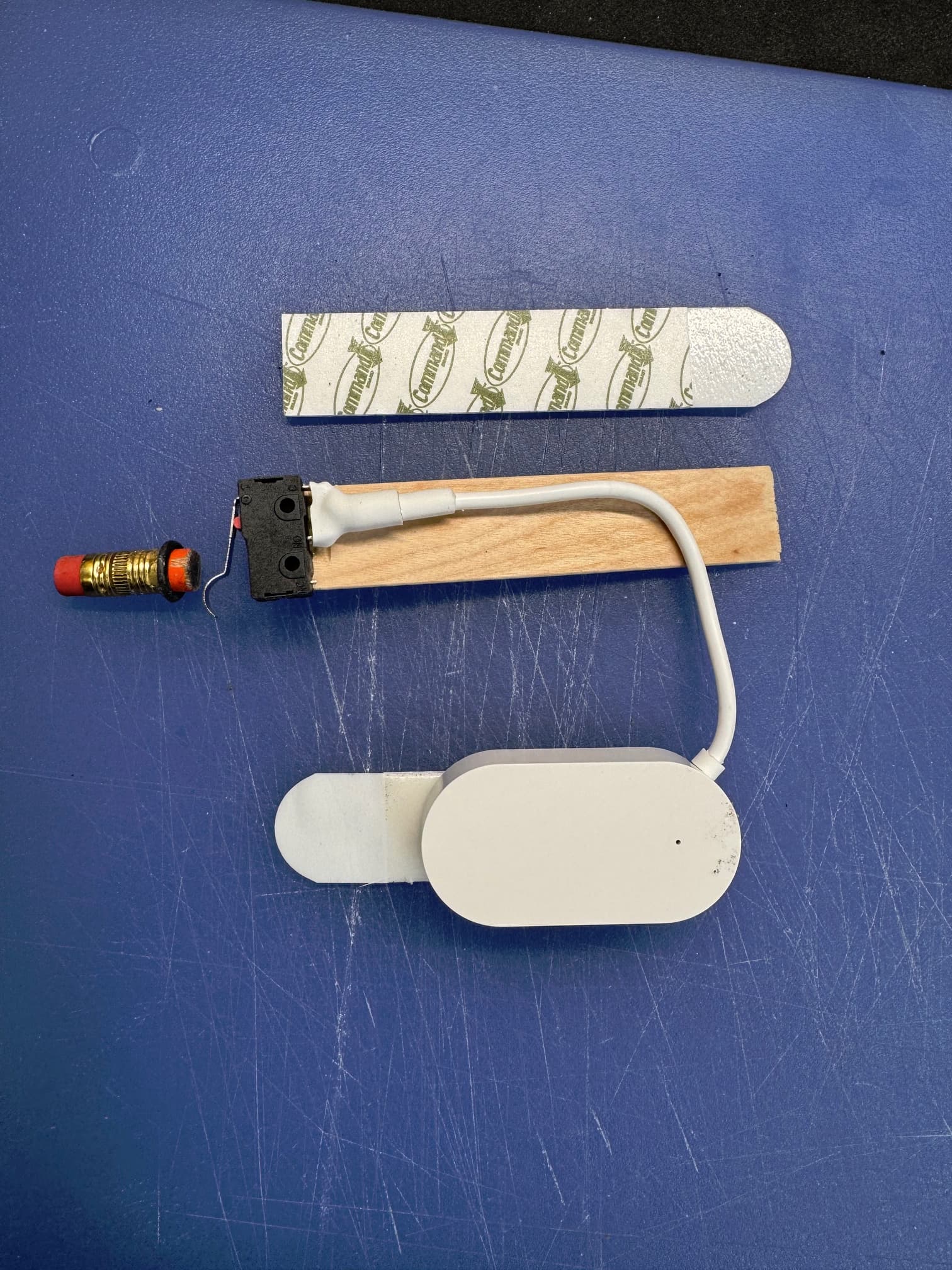
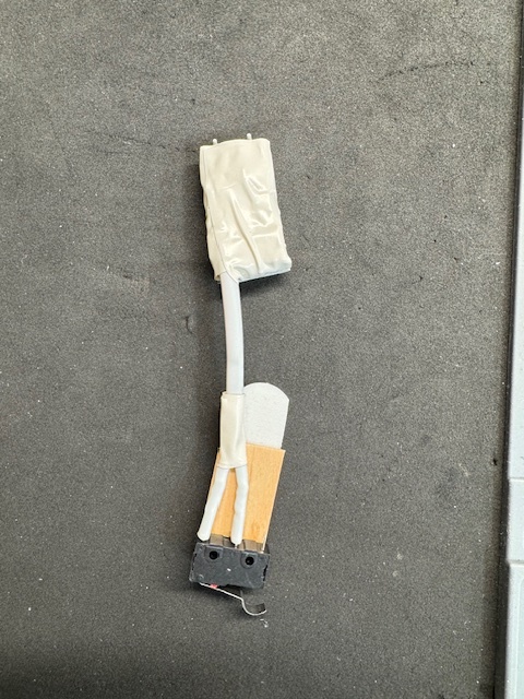
I'm hoping that this jury-rigged setup will inspire some other solutions (including commercial solutions). I think a micro-switch plunger protruding into the latch channel and integrated into a small housing with a Zigbee radio (maybe with an external antenna wire?) would be a more elegant and reliable solution.

6 Likes

That’s very clever!!

I did something like this a few years ago on all of my doors but slightly differently. I just fitted a lever microswitch into the keep in the frame (or opposing door in the case of my bi folds). Depending on the door, either the multipoint locking hook or mortice bolt pushes that microswitch closed when locked. The microswitch is wired into the input of an Aeotec Z Wave contact and the status of all locks is shown on my dashboards around the house. There's no need to check the door/wonder whether I locked them. For UK PVCu doors it's just a case of removing the full length strip in the frame and securing the microswitch behind it.

1 Like

I'm actually headed in that direction, as I'm not convinced that the magnetic contact sensor solution is the best. Last night, I ordered these 2 items from Amazon:

Micro-switches small enough to fit within the door frame latch channel:

Zigbee water leak sensor that runs on AAA batteries:

1 Like

OK, the Zigbee water sensor pictured above arrived, and it's a dud. The Amazon website said it had a depth of .47 inches, when in fact the depth is about .76 inches. I needed less than .5 inches to fit within the sliding door frame channel without being crushed by the door when closed.

I might have to crack open an Aqara magnetic sensor -- the shallowest sensor I've found -- and try to solder a switch in parallel with the reed switch, then coat everything in a plastic potting material.

Having said that, the magnetic solution described above is actually working pretty well, except that opening the lock but not sliding the door open doesn't cause the Aqara sensor to register as OPEN (thus, a false negative). The door has to be opened an inch or two to make the sensor change from CLOSED to OPEN; I suspect that the steel frame in the door might propagate the magnetic field to the sensor sufficiently such that the sensor doesn't change state, even though the magnet has dropped down to its rest state (or so I think -- I can't actually see the pencil and magnet until I open the door). So my current prototype fails to detect a door that has been (a) unlocked but (b) not opened.

My variation of your basic plan: You can get microswitches with rollers:

Screenshot 2025-02-03 at 11.17.45 PM

swap the pencil with magnet for a pencil with a bevel at the top and when it slides UP it rolls along the microswitch and makes or breaks the contact. Run the microswitch contacts to the internal contact points of the reed of that Aqara Zigbee unit.

In the unlocked position, the bevel of the pencil is below the roller, allowing the microswitch to be Open. When the lock is closed, the bevel then the pencil body rides up the microswitch roller and into the Closed position.

I'm on the same page -- but since I didn't know exactly what would work, I ordered the following a couple of days ago:

And tonight, I ordered a Tuya Zigbee water leak sensor similar to the sensor pictured above, but using a coin battery (and is thus thinner in depth). I expect I'll still have to liberate the electronics from the plastic shell to meet the depth limitation imposed by the door frame, but I'm thinking white electrical tape will help with the WAF.

This post is about a prototype non-magnetic contact sensor for a sliding patio door LOCK.

The sliding door and lock I'm working with are pictured in post #1.

The first picture shows all of the parts:

I took a Tuya water leak sensor that included a cable to a pair of electrodes, cut the cable down to expose two wires, and soldered the wires to the terminals of a micro-switch. A bit of shrink-wrap tubing added for aesthetics (improved WAF).

The switch is glued to a cut-down tongue depressor (needs to be thin to fit the door channel such that the sliding door closes fully).

A bit of cut-down pencil with an O-ring glued to it as a stop fits in the lock channel. The lock mechanism pushes upwards on the eraser end when the door is locked sufficiently to change the switch state.

3M Command strips are used on the back of the tongue depressor and in the door channel to allow adjustable positioning of the switch. The sensor was going to be set up the same way BUT the 2 layers of strips was too thick, so I used a single thin 3M poster mount strip.

The mounted sensor and switch are shown in the second image:

This works better than the magnetic prototype in post #1 because the switch opens and closes at the same physical point and the sensor changes state when the door is unlocked but not opened (the magnetic prototype had to be unlocked AND opened for the magnetic contact sensor to indicate OPEN).

To avoid using "wet" and "dry" states in my rules, I changed the driver to "Generic Zigbee Contact Sensor (no temp)". Accordingly, I now get "open" and "closed" states.

HOWEVER, I connected the Common and Normally_Open terminals of the switch to the leak sensor, which means the sensor state is WET (which translates as OPEN in the contact sensor driver) when the door is closed, and DRY (which translates as CLOSED) when the door is open. Fortunately, I have a second sensor and many more microswitches, so I'll correct the error by building a 2nd unit using the Common and Normally_Closed terminals. I'm also likely to paint the wood portion and the switch white for even better WAF.

Here's a picture of my 2.5 version -- correctly connected (with removable spade terminals) and more compact (the tilt on the sensor is due to the short wires coming out of the side rather than bottom of the sensor).

OK, ran into a snag -- the water leak sensor I was using sends out "wet" state signals every 5 minutes when the door is unlocked (micro switch is OPEN), and the battery drain is fierce (40% in a week).

So I've hacked an Aqara magnetic contact sensor (as others have done) like the first picture below (which is not mine, but my sensor with added wires looks identical except that I solder my wires). I did cut the glass reed switch out to avoid stray triggers that might be caused by jostling when the sliding door shuts or opens, and of course a magnet no longer works to change the sensor state.

I added spade connectors to the other ends of the new wires, taped everything up (leaving access to the Aqara's battery holder and tiny reset micro switch), slapped on some Command strips (which can now go on the sensor since the case is mostly gone and it is thin enough to mount in the limited space available).

I started tonight with 100% battery and will see how long the battery lasts. I suspect that it should be fine because a contact sensor is not biased to more frequently report one state (wet/open) over the other (dry/closed).


OK, here's my final design for a sliding door patio lock open/close sensor.

I took an Aqara Zigbee magnetic contact sensor, carefully opened it up, and hooked 30AWG wires to the ends of the reed switch (both of the following photos are pre-soldering and trimming of the wires). The Aqara sensor is only about 11mm high and JUST fits in the sliding door channel without blocking (or being crushed by) the door when closed.

In a previous version, I cut the glass shell of the reed switch, but I left it this time thinking that I might eventually reverse the process if I found a better lock open/close sensor, but I apparently damaged the reed switch during soldering and it no longer responds to a magnet.

I filed a small notch in the white cover of the sensor to feed the wires through without pinching. The notch is barely visible in the first photo at the bottom edge, left side, of the white cover.

I reassembled the sensor, taking care to put the little white button back in the correct orientation -- the "U"'s of the button mate with ridges in the white cover. I added a dab of clear glue where the wires exit the white cover for some strain relief.

I then connected the other ends of the wires to a closet open/close (NC) switch as shown in the next photo, using shrink tubing to cover all wiring. The 30AWG wire was so thin that the screw-clamps in the closet switch would not clamp properly (the wires easily pulled out), so I crimped spade lugs to the wire ends and soldered the wire to the lugs for good measure. I had to file off a couple of protrusions on the spade lugs to fit the holes of the closet switch, easy work.

I also made a "T" shaped plunger by gluing two pieces of 10mm X 10mm square acrylic rod. The top of the "T" is about 35mm wide; the other portion is about 15.75mm high and fits perfectly in the sliding door catch (see last photo).

The next photo also shows my prior version which coupled just the circuit board (covered by white electrical tape) of an Aqara contact sensor to a micro-switch.

The last photo shows the sliding door lock open/close assembly in position. The acrylic "T" just sits in the door catch. The closet switch plunger has a throw of about 8.5mm, BUT switches from CLOSED to OPEN with around 1mm of travel. The sliding door latch "hook" (see photo in post #1) is about 9mm high. So the closet switch plunger can be placed within a few millimeters away from the top of the "T", so I no longer needed a hook-and-loop or the like mounting to allow adjustment, just 3M mounting tape. The Aqara sensor is also mounted with a ring of 3M tape that came with the product; positioning the sensor is not critical.

The wires are longer than I'd really like, but I had trouble stripping the 30AWG wire without cutting it completely (even with a tool that supposedly works with 30AWG), so I opted for longer wires and stripped both wires until I managed to get stripped wires the same length on both sides.

HOWEVER, despite the long wires, I did get a "nice job" from my spouse, so this implementation has a high WAF (of course, it's not visible 99% of the time).

The driver for the Aqara sensor is "Zigbee - Xiaomi/Aqara Contact Sensor". This driver allows inverting the open/close state of its inputs, which is needed because the closet switch is OPEN (plunger depressed) when the sliding door is locked.

Note that I created a virtual lock device that gets set to LOCKED or UNLOCKED by a Rule Machine 5.1 rule, triggered by the contact sensor state, so that the sensor is perceived, by means of the virtual lock, in other aspects of Hubitat as a "lock" rather than as a "contact sensor". The rule also sends some notifications (to Inovelli Blue dimmer/switch LEDs next to the sliding door and in my office) based on the OPEN or CLOSED state of the pictured lock state sensor.

Enjoy!

4 Likes

This is awesome for those whose sliding doors have that type of latch. Terrific work and particular thanks for sharing!