OK, here's my final design for a sliding door patio lock open/close sensor.
I took an Aqara Zigbee magnetic contact sensor, carefully opened it up, and hooked 30AWG wires to the ends of the reed switch (both of the following photos are pre-soldering and trimming of the wires). The Aqara sensor is only about 11mm high and JUST fits in the sliding door channel without blocking (or being crushed by) the door when closed.
In a previous version, I cut the glass shell of the reed switch, but I left it this time thinking that I might eventually reverse the process if I found a better lock open/close sensor, but I apparently damaged the reed switch during soldering and it no longer responds to a magnet.

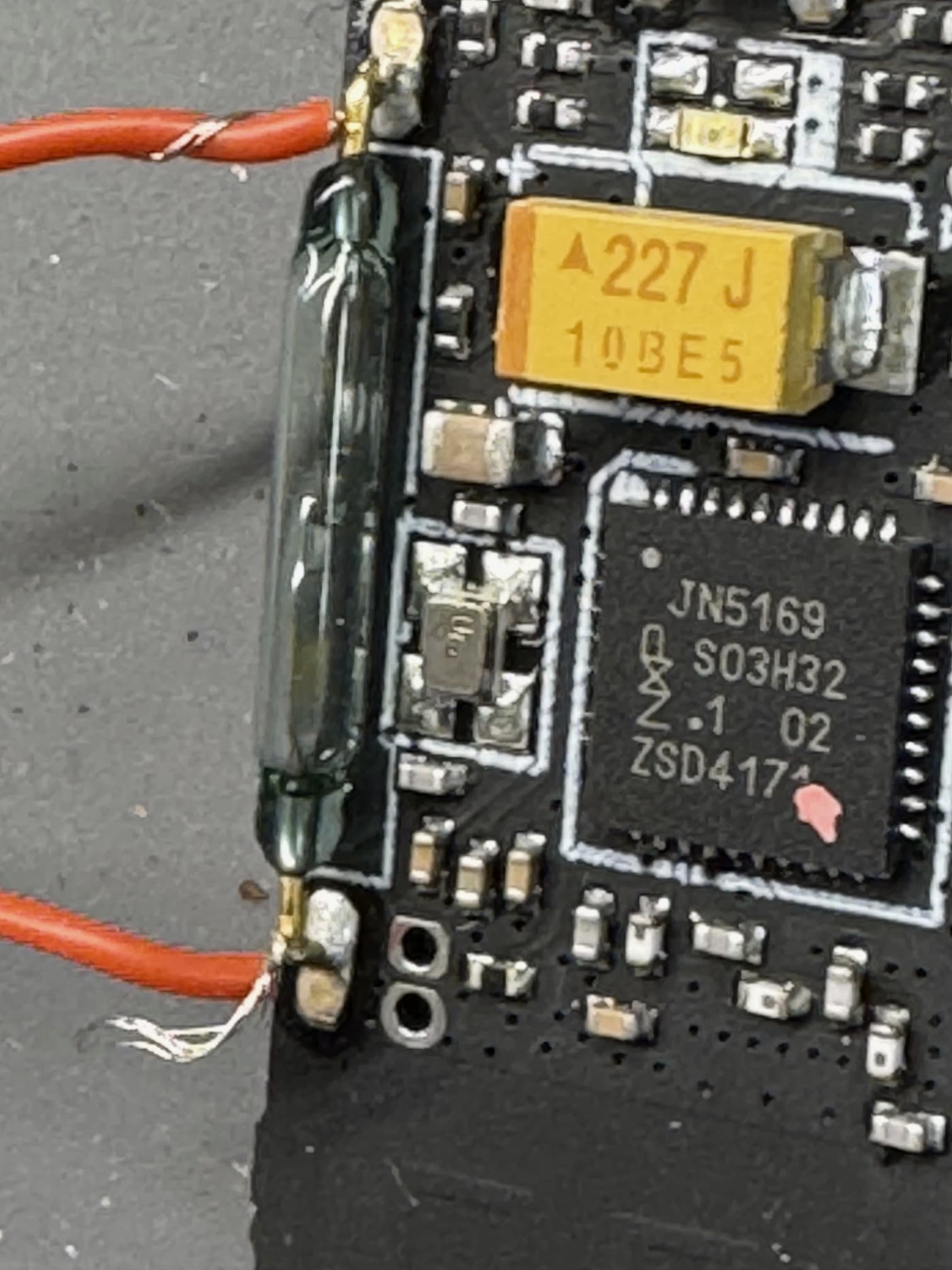
I filed a small notch in the white cover of the sensor to feed the wires through without pinching. The notch is barely visible in the first photo at the bottom edge, left side, of the white cover.
I reassembled the sensor, taking care to put the little white button back in the correct orientation -- the "U"'s of the button mate with ridges in the white cover. I added a dab of clear glue where the wires exit the white cover for some strain relief.
I then connected the other ends of the wires to a closet open/close (NC) switch as shown in the next photo, using shrink tubing to cover all wiring. The 30AWG wire was so thin that the screw-clamps in the closet switch would not clamp properly (the wires easily pulled out), so I crimped spade lugs to the wire ends and soldered the wire to the lugs for good measure. I had to file off a couple of protrusions on the spade lugs to fit the holes of the closet switch, easy work.
I also made a "T" shaped plunger by gluing two pieces of 10mm X 10mm square acrylic rod. The top of the "T" is about 35mm wide; the other portion is about 15.75mm high and fits perfectly in the sliding door catch (see last photo).
The next photo also shows my prior version which coupled just the circuit board (covered by white electrical tape) of an Aqara contact sensor to a micro-switch.

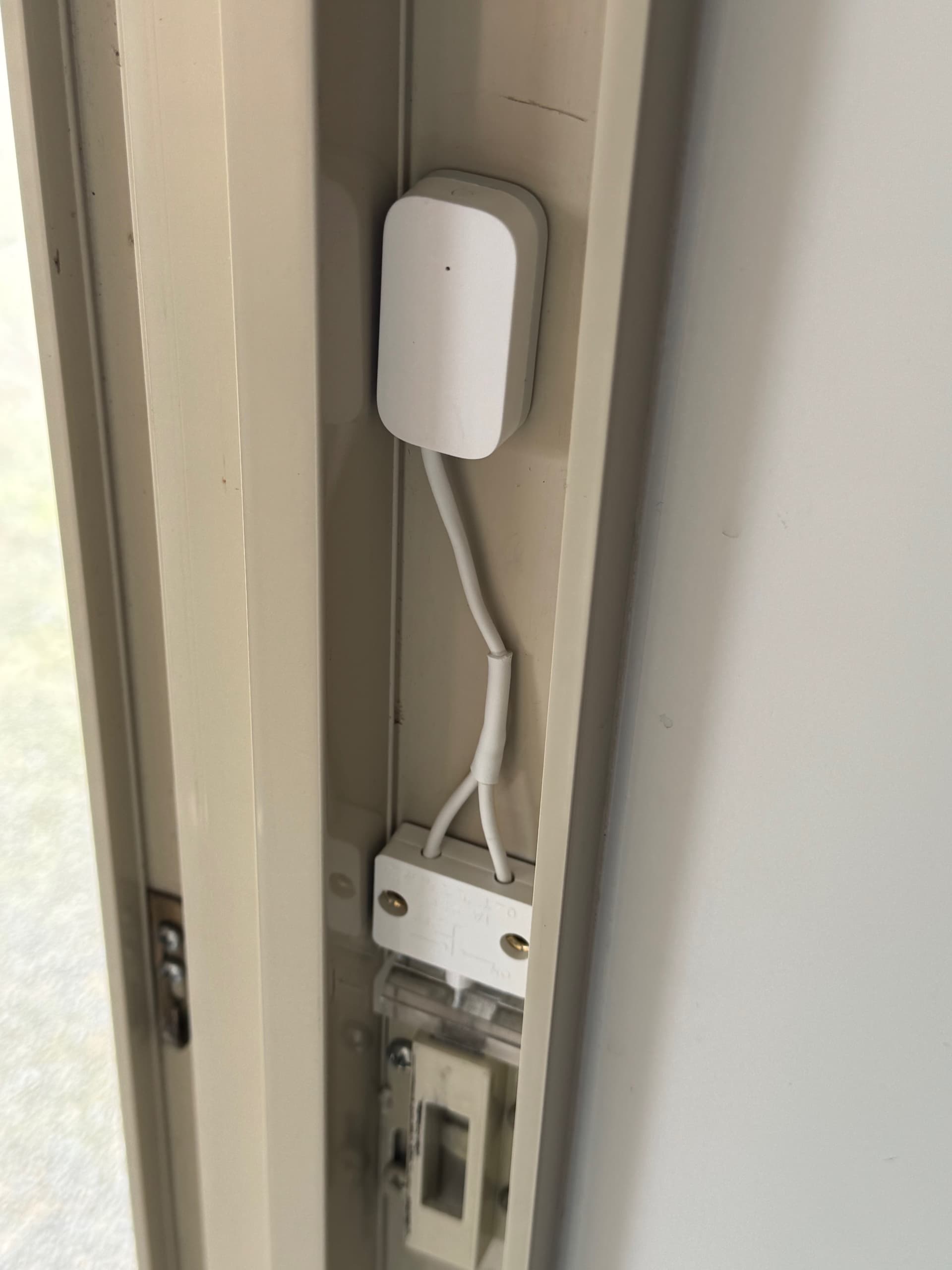
The last photo shows the sliding door lock open/close assembly in position. The acrylic "T" just sits in the door catch. The closet switch plunger has a throw of about 8.5mm, BUT switches from CLOSED to OPEN with around 1mm of travel. The sliding door latch "hook" (see photo in post #1) is about 9mm high. So the closet switch plunger can be placed within a few millimeters away from the top of the "T", so I no longer needed a hook-and-loop or the like mounting to allow adjustment, just 3M mounting tape. The Aqara sensor is also mounted with a ring of 3M tape that came with the product; positioning the sensor is not critical.
The wires are longer than I'd really like, but I had trouble stripping the 30AWG wire without cutting it completely (even with a tool that supposedly works with 30AWG), so I opted for longer wires and stripped both wires until I managed to get stripped wires the same length on both sides.
HOWEVER, despite the long wires, I did get a "nice job" from my spouse, so this implementation has a high WAF (of course, it's not visible 99% of the time).
The driver for the Aqara sensor is "Zigbee - Xiaomi/Aqara Contact Sensor". This driver allows inverting the open/close state of its inputs, which is needed because the closet switch is OPEN (plunger depressed) when the sliding door is locked.
Note that I created a virtual lock device that gets set to LOCKED or UNLOCKED by a Rule Machine 5.1 rule, triggered by the contact sensor state, so that the sensor is perceived, by means of the virtual lock, in other aspects of Hubitat as a "lock" rather than as a "contact sensor". The rule also sends some notifications (to Inovelli Blue dimmer/switch LEDs next to the sliding door and in my office) based on the OPEN or CLOSED state of the pictured lock state sensor.
Enjoy!