Project: Upgrading WaterCop (AT&T Digital Life model) to reliable Z-Wave Plus

Like many of you, I have one of the Z-Wave Fortrezz WaterCop valves that were sold on Amazon and elsewhere which were part of the AT&T Digital Life ecosystem back in 2013. These are NOT the same as the current version of WaterCop by DynaQuip. These WaterCops are notoriously prone to drop off frequently, and require regular power cycles, especially after a hub reboot, to remain responsive.

WaterCop disavows these Digital Life devices and says they should not have been sold, but does offer a discount on the current model. Still, the discounted price is about four times what I paid for the old model, and still isn't Z-Wave Plus. So that's not a solution I'm interested in.

The inside of one of these looks like this:

Shorting the two Water Probe terminals does close the valve. But you can't open the valve this way.

On another model (not the Digital Life one), there is an 8-conductor Aux I/O connector external shown here,
AuxIO

whose contacts are documented in the watercop-watercop-z-wave-flood-prevention-system-installation-manual. 5 is Close, 6 is Open, and 7 is +5VDC with momentary contact to activate. I'd like to connect these with two dry contact relays based on Z-Wave Plus (such as Fibaro FGBS-222) which can be powered from the 12V that powers the valve itself. Valve state is reflected in the Aux I/O connector and that could optionally be useful.

It is tempting to think that the 8-conductor jack would connect at P9, but the etch says these are four jumpers. The header at P6 is probably it since 2 of the 8 conductors on the jack are GND, which may not require a header pin if the jack is mounted to GND. There is some testing I can do to verify that, such as testing continuity between these pins and the two screws on the Water Probe. First, wanted to ask here if anyone has done or attempted to do something similar. If not, I'll share my results as I go.

I converted a WaterCop Classic to additionally accept, along with the WCC's original transmitters, Z-wave leak detectors (Intellitech). I talked about it here.

Before I converted, I bought a pretty cheap z-wave WaterCop valve that the Ebay guy said was newer version, but who knows. I just went down to the basement and took some pictures. No Aux input jack like my Classic has.

Where do those three wires go? Maybe to the motor on the valve? It says: power, close and open. What's that terminal on the right?

Good info in the other thread. Thanks. I'm OK on the sensor side as I have Samsung leak detectors all over the house, not WaterCop sensors. Also, the ZEN16 would serve my purposes well. For some reason I was thinking the Fibaro would be better for piggybacking on the valve's 12V supply, but either should work as well.

Do you still have your Classic? Do you happen to know where the RJ45 contacts connect to the logic board? I'm pretty sure it would be the headers at P6 where pins where pin 1 maps to connector position 2, 2 to 3, etc, but it would be fabulous to have a picture.

As for the three wires at the top, they go to the valve motor itself. I thought those might be inputs at first but they, along with contact switches that the rotation of the valve engage, make it go open and closed.

The connector on the right is 12V in. Other two screws labelled BKP+ and BKP-? Breaker panel? Backspace? Bookkeeper? :slight_smile:

I'd be real nervous about taking it apart.
edit: It's in service.

Well, I certainly understand that. I will just say that there are four Philips screws on the four corners of the control side, that when removed, allow it to be lifted away exposing the bottom. But I understand completely.

Here you go.
You can probably figure out where the jack is: a little to the left and down from the red dip switch.

1 Like

How about 12v backup power, like for a battery?

1 Like

Thank you, sir! You may have saved me a lot of wasted effort since the RJ45 doesn't simply plug in to any headers at all. This is a completely different PCB from 2007. I may should take a different tack.

I looked at eBay, and while several of those people are selling are the AT&T ones that are no good, the one you are talking about at $55 does seem to be from 2019. Did you receive yours? Try it out?

Yes, I paid 55 for mine on ebay as well. I didn't try it out since I got the other one working with the Classic's detectors as well as z-wave. I took it out of the box earlier and took some pictures of the labels, front, etc, if that would be helpful to you.

It's your equipment that'll fry, lol, but I wonder if you connect the red wire to green it'll open, and red to white it'll close? Maybe the limit switches on the shaft will turn off the motor when it gets to position.

You're totally bypassing zwave anyway and basically just using the motor operated valve, so why not just have the Zen 16 relays turn on power to either the white or green wire? If my theory is correct?

edit: if you didn't want to keep the relay on, you could have it turn off in 5 seconds or so after the valve opens or closes. Zen16 can do this.

That's an intriguing enough idea that I will test the voltage on those wires during open and close to see if they behave as we'd expect. The one thing I'd lose there is a status of the state of the valve, as well as the ability to control the valve at the valve by pressing a button (without adding a button; also I could still turn the valve manually). Something to think about.

Still those pins at P6 are interesting, particularly since it is right beside a "close" control. I'm going to play around and see what I learn. As Khan might say, "It tasks me. It tasks me".

A guy on the ST community recently “upgraded” his faceplate to the latest which still isn’t Zwave plus. He includes a picture of the board

1 Like

Thanks. Interesting. That's the exact same PCB that's in the failing ones. The difference must be firmware.

$121 is cheaper than buying a whole new Watercop, for sure. But it is still Z-Wave. I'm going to pursue the $40 solution that gets me to Z-Wave Plus.

Got nowhere trying to Easter egg this thing. Determined the GND pins for P6, P7, and P12. Found potential between some pairs of pins but didn't want to just start shorting pin pairs to see what happens, although it seems obvious that somewhere there are connections for momentary closure to open or close. The PC board is more complex than I expected .. at least double sided if not multilayered, so tracing connections is not practical (oh, I should mention the board is attached so it can't be removed non-destructively. What could all those headers and jumpers be about, anyway?

I may end up using a Z-Wave Plus relay to close the Water Probe to ensure it gets the close message when needed. Or buy the one off eBay that appears legit not one of the bad ones. Or fix this in software by issuing a close on the valve, wait 10 seconds, power cycle the WaterCop, wait 10 seconds, then repeat several times.

Following up to tie up loose ends in this thread. First of all, my initial objective to convert the AT&T 2013 version of WaterCop to Z-Wave+ was never achieved. I got into a very good conversation with a support person at DynaQuip who was remarkably willing to discuss the issue and possible solution. It turns out that the header pins on the board are there for the purpose of programming the device, and as far as could be determined, nowhere on the board were there easy connections to close to initiate a valve open. The Water Sensor connector obviously could be used to trigger a valve close.

I ended up purchasing the 2019 version of the WaterCop for $55 (actually a little less) from the eBay seller mentioned above. As noted in looking at the one
@velvetfoot posted, the PCB is identical to the 2013 model. However, there are likely differences on the unseen side of the PCB and/or firmware, as this one has not dropped of the mesh in two weeks of observation. The motor sounds a bit labored/grindy which concerns me a bit but it turns the valve. And it does appear to be as described by the seller with a manufacture date of 2019. DynaQuip had previously told me the models since 2013 should be reliable, albeit Z-Wave, not plus.

1 Like

Good to know if my Classic ever craps out.
Have you figured out what sensors you're getting?

All my leak sensors are Samsung.

1 Like

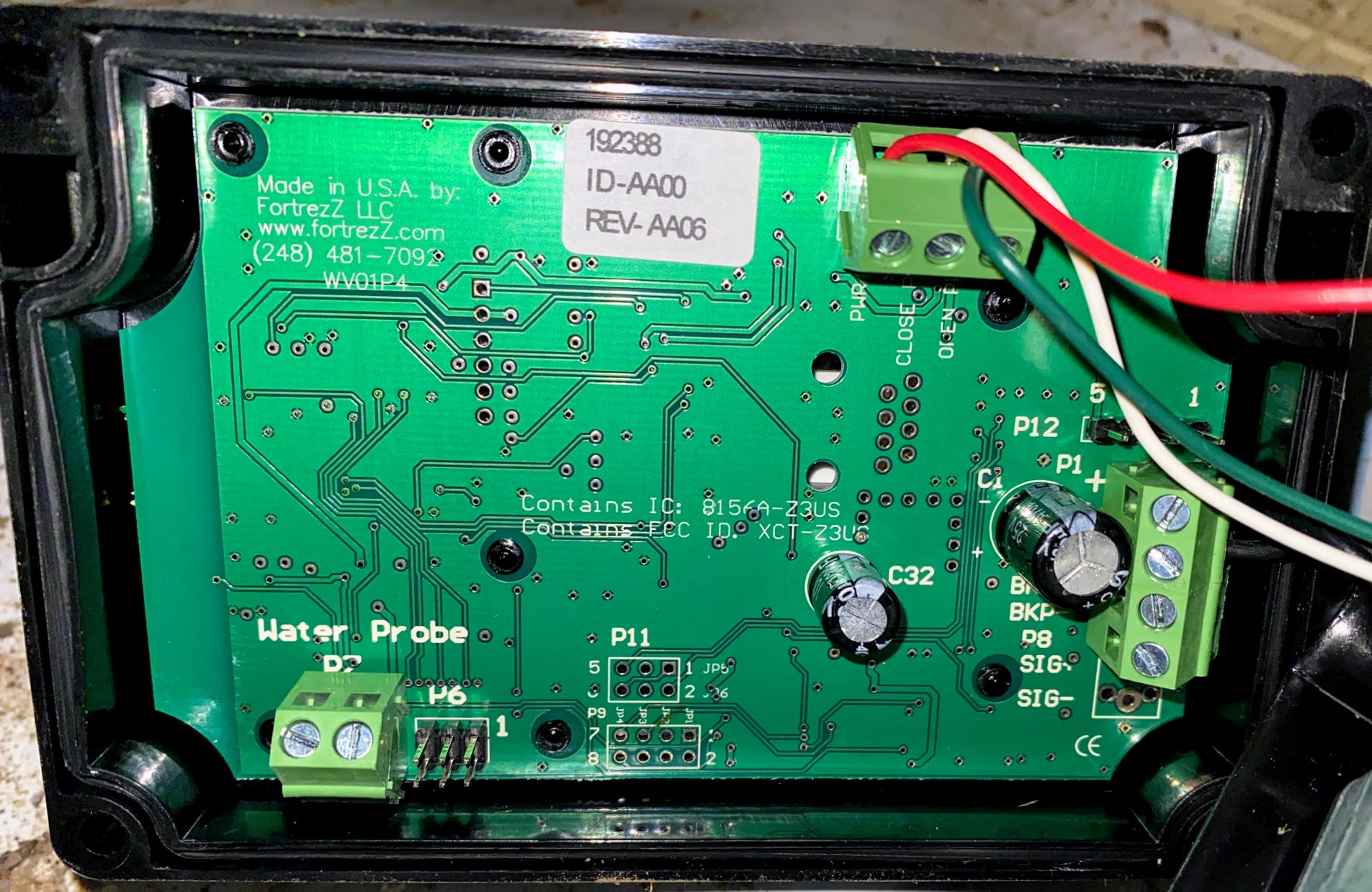
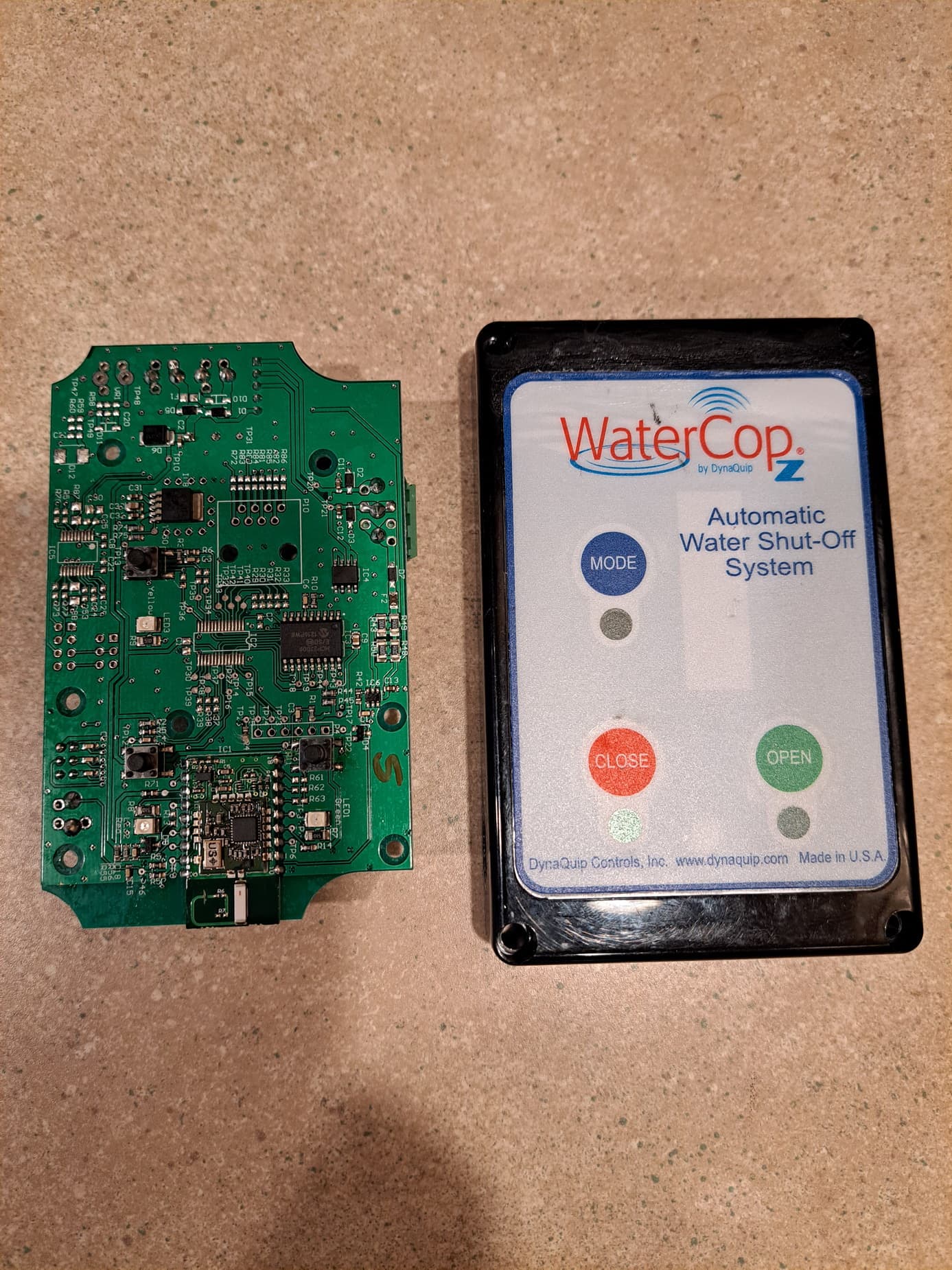
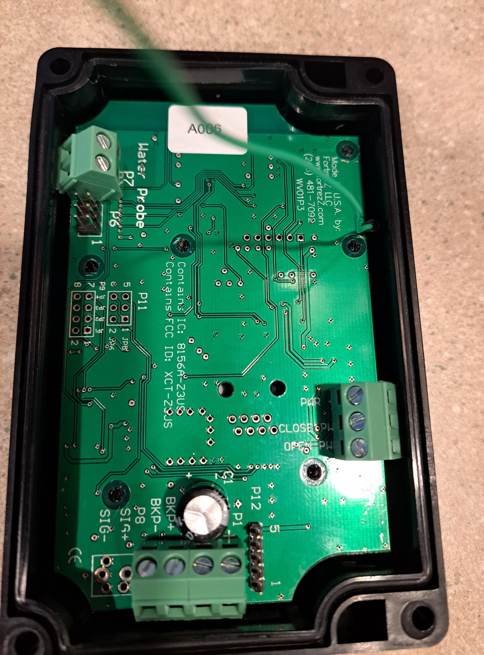
Sorry for necroposting this thread, but I couldn't find any pics of the other side of the circuit board. I took mine apart (the Zwave stopped) and thought I'd use this thread to archive the pics for the community.

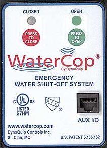
I had the Classic version of this valve in my last house, controlled by an Omni Pro II. It worked well. However that model had no manual capability to move the valve. So I really want to use this model in my new installation.

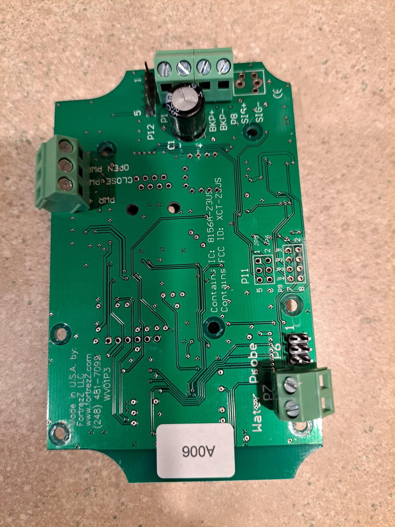
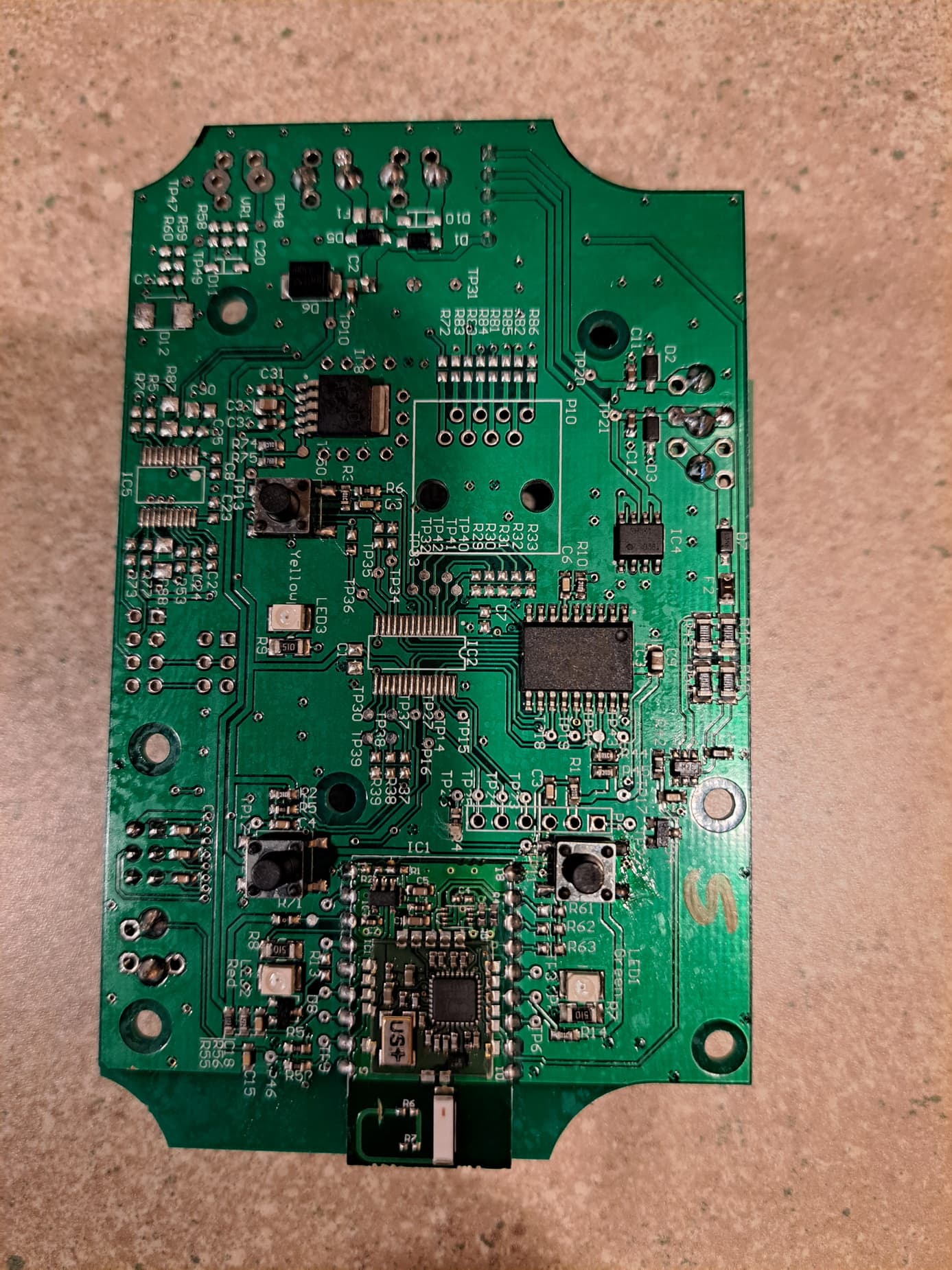
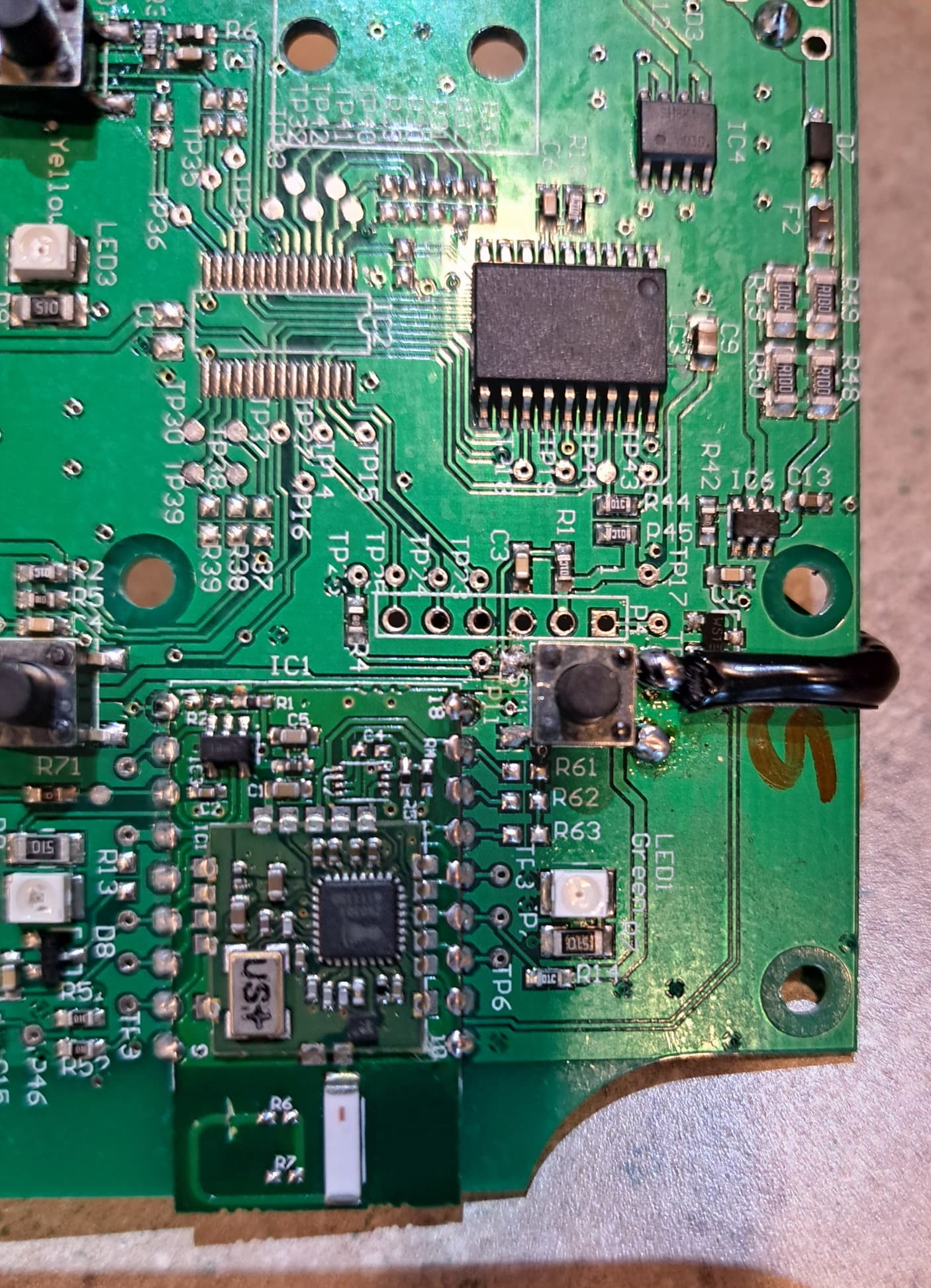
Looks like the Zwave antenna trace got cut (I have no idea how that would have happened) that explains no comms.

Did some testing.
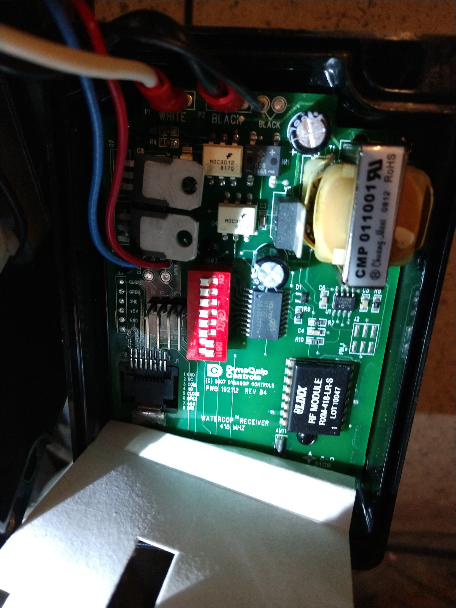
On the P7 header, the lower terminal is ground. As we knew, shorting the two together closes the valve and changes the status LED to red once the valve is in the closed position.

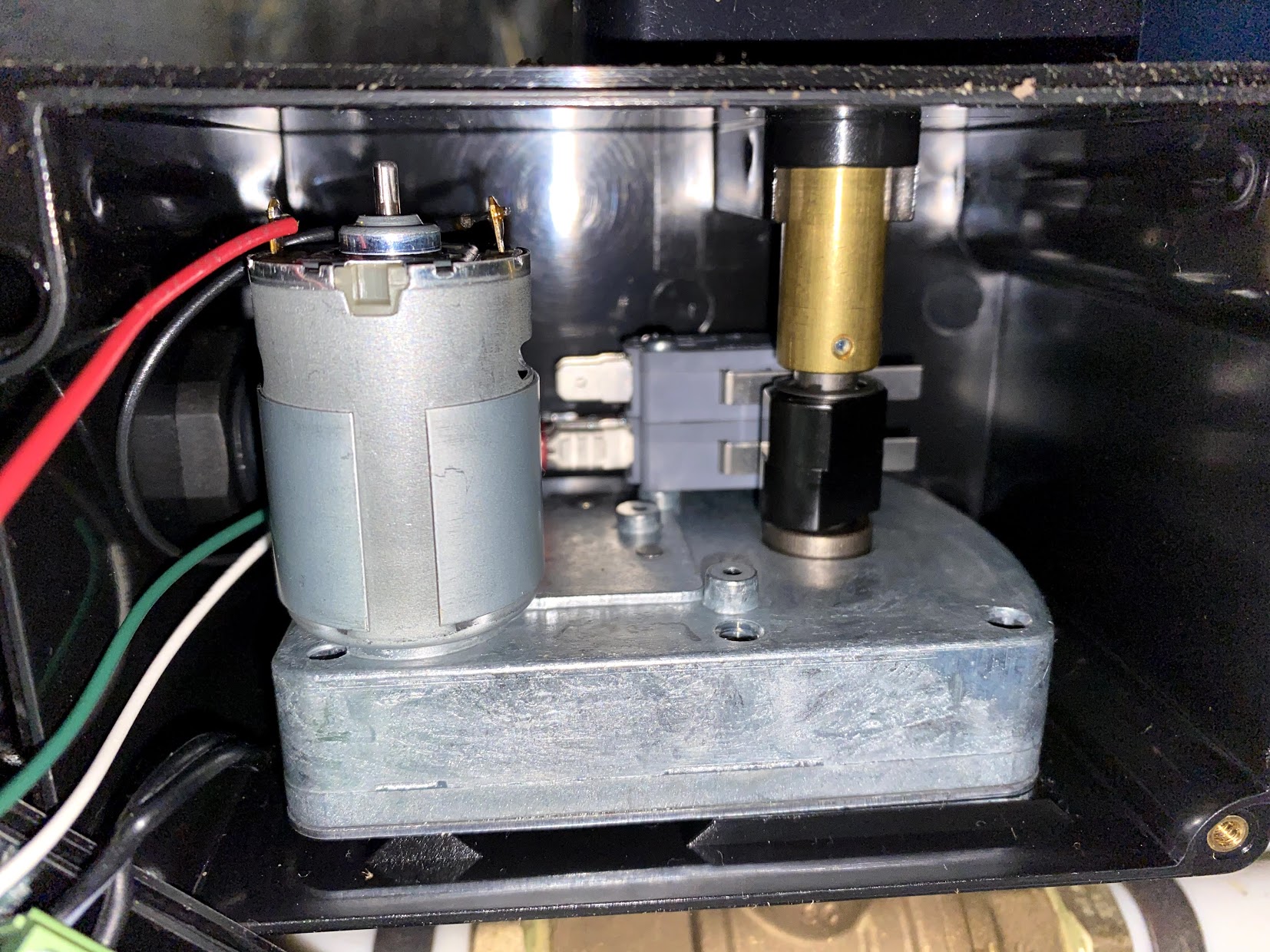
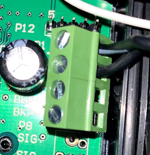
On the motor header.
The red "PWR +" terminal is +12VDC. (It has to be filtered because there is not direct continuity to the power supply +12VDC terminal
The white and green wires are variably open circuit or ground depending on the operation.

With the valve closed:
The green "OPEN PWR" wire has continuity to the other side of the motor, but it is open circuit.
The white "CLOSE PWR" wire is grounded and there is 12VDC between it and the red wire.

With the valve open:
The white "CLOSE PWR" wire has continuity to the other side of the motor, but it is open circuit.
The green "OPEN PWR" wire is grounded and there is 12VDC between it and the red wire.

With the valve closed:
Shorting ground from the P7 ground terminal to the green wire will operate the valve. The ground has to be applied the entire time the valve is in transit (~3-5 seconds). The mechanical switch operated by the cam will stop the valve in the correct open position.

With the valve open:
Shorting ground from the P7 ground terminal to the white wire will operate the valve. The ground has to be applied the entire time the valve is in transit (~3-5 seconds). The mechanical switch operated by the cam will stop the valve in the correct closed position.

When the valve is operated in this manner the LEDs and front control buttons DO NOT update correctly.

If the valve is closed and the red LED illuminated, and the valve is opened by shorting to the green wire, the valve will open, there will be 12VDC between the white and red wires, but the red LED will remain illuminated and the close button is inoperable. The logic "thinks" the valve is still closed.
In this condition shorting the P7 header has no effect even though the valve is physically open.

With the red LED illuminated and the valve open, pressing the open buttons simply updates the LED and buttons. The valve doesn't move, the green LED illuminates, and the close button and P7 header now become operational. The same thing happens if the green LED is illuminated and the white wire is shorted to close the valve.

So:
You can operate the valve via dry contacts shorting the green and white wires to ground for a few seconds, and you can monitor position status by running the 12VDC out from the green and white wires to relays connected to dry contact inputs or a voltage sensing circuit. The downside is the front control status lights and buttons get out of sync. If you don't need that capability, there is no reason to remove the board to get at the other side.

I used a soldering iron to carefully melt the plastic posts holding the board in to the top cover. It can be superglued back.

In order to operate the valve via external relays and preserve the front panel status and control, I need a way to operate the open button. The open button lower legs are ground. Momentarily shorting ground to the upper leg of the button initiates the open action the same as pressing the front button. So I will solder a small wire to the upper leg of the switch and borrow the ground from the P7 header. With that in place the P7 header can operate the close function and all status and front panel controls will be preserved. I'll still use the 12VDC out from the green and white wires to monitor valve position remotely.

A plus is I'll be using Zigbee. I have an extensive Zigbee mesh already.

ETA: Got the wire soldered on, works perfectly to control the valve. I need some inputs to signal valve status. I haven't found a Zigbee IO module that takes a low voltage/12v trigger as an input and signals a state with Zigbee. I think I can hack the Sonoff Zigbee light switches that go inside the J box and take a snap switch input. I can use a 12V relay triggered by the valve state signals to trigger the Sonoff switch and monitor state via Zigbee that way.


3 Likes