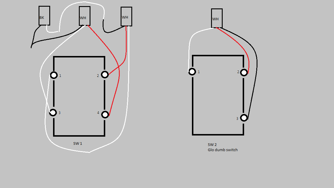
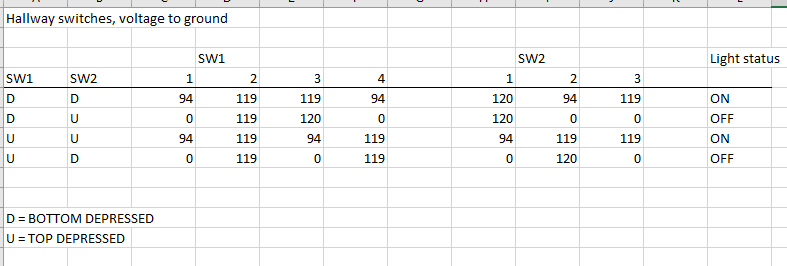
I'd like to replace the 4-way with an Inovelli Black. I have what appears to be a 4-way switch and a dumb 3-way that control two ceiling lights. There is a neutral available in the box. It is very difficult to determine what feeds are going where. Below is a diagram of the existing wiring and a table of the voltages on the switch terminals. Drawing is looking at the front of the switches. I did also post this to the Inovelli forum but no luck there so far. Note. SW2 is a "glow" 3-way switch with an internal neon lam to illuminate it. I'm pretty sure that accounts for the 94 v readings.
Inovelli forum post
Check out Lutron's three-way instructions for the Caseta. Please don't simply follow these instructions, but it may help. I think you have two normal three-way switches with the usual traveler in screw #4 (assuming that's the off-color screw).
Wouldn't a four-way switch setup have three switches? I'm wondering if this isn't a typical three-way switch, with the extra wires continuing on to other unrelated outlets/switches. From what I understand and in my experience of trying to figure out 1960's wiring, wire color doesn't mean too much but what's wired to which screw terminal does.
The voltage readings suggest that SW1 is internally wired as a normal 4-way. SW-2 and a normal 3-way. One would expect the one of the 3 conductor cables would go to a second 3-way but there is none. This was done in 1970. I have another ceiling fixture to open up. Hopefully the additional 3 cond will be terminated there and will shed some light on what it is doing. I've got time tomorrow to look into it.
This is not a typical circuit. You are missing a 3 ways switch somewhere and you will need to find the line wire as well. Looking at your voltage. It looks like you don't have neutral. Are you using the bare ground as your neutral for measuring those voltage?
I would label all the wires (taking picture works as well). Remove all the wires from both switches and find out the Line (power wire from the breaker) and neutral first. Use your ground as a neutral reference point for measurement.
Once you find out the line wire. The next step is to find the neutral by using the line wire as your reference point.
You should also measure resistance and find out which bundle from the 3 ways is at the 4 way switch. This bundle is usually called the traveler.
With all this. I still think you are missing a third switch hidden somewhere.
Be sure to turn off the circuit breaker when measuring resistance or connect/disconnect wires.
I know for sure that the middle cable goes to SW2. It certainly looks like there should be an additional 3-way but it is not available. One guess is that it is a box that was covered during construction. These two switches control a pair of ceiling fixtures. One has a two cond bk/wh cable feeding it. the other is a junction for four 2 cond bk/wh cables, a pair of which are spliced into the lamp. All measurements are to copper ground. Disconnecting everything is a project because the splices were soldered instead of wire nutted. In the end this may be a case where a couple of smart bulbs are easier than messing further with a switch.
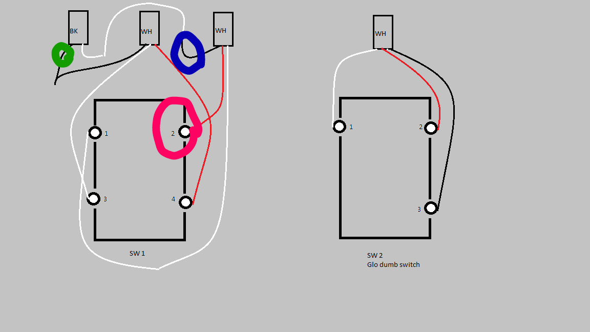
My guess would be this.
The green circle is load.
The red circle is Line.
The blue circle is neutral.
You mentioned there is neutral in the box. Can you confirm the neutral wire? You can check by having your meter between the blue and red circles and have 119 volts regardless of switch positions. Also turn off the breaker and measure resistance between the blue circle and ground. Should be less than a few ohms.
Can I ask what feels like a really dumb question....why are some of your recorded voltages only 94V? Aren't they supposed to be ~120 or ~0? What's 94?!?
Floating voltage. Range between 60 to 100 depending on the type of meter you are using. This is common in an used wire or no load wire that's in the same conduit as the one with line voltage.
Oh...ok.
Well, don't we know that Sw 1 # 2 is the line since that's the only one that's hot all the time?
Also, the OP says:
Wouldn't that mean that none of these are the neutral? Which would be typical if these are the dumb switches before installing the inovelli. Right?
Sure, we can assume sw1 #2 is line but because this is not a typical 4 ways switch circuit so there is a hidden switch somewhere which is confusing. You usually don't use a 4 ways switch in a 3 ways circuit.
Correct. None of the wires connected to the 2 switches are neutral but there are 2 wires connected together from BK white wire to WH white which could be a neutral.
And your blue circle is the one you think is neutral, right? Sometimes electrical work makes me feel very dumb. Some of this stuff is so counter-intuitive!!!
P.S. I didn't know that trick about neutral but as soon as i read it I had a classic face-palm moment. It was like...wait for it....a light bulb went off!!  (Sorry, I couldn't help myself.) Thanks for taking the time to answer my questions. I appreciate it.
1 Like
I had a chance to get back to this. I disconnected the wires from SW1 and the black from SW2. Killed the power and dug out my toner and probe. C3 goes to a third switch and or cable terminations buried in a nearby wall at switch height. C3 RD and BK are always connected and go back to C1 white which is always hot. C1 BK is neutral. Seems like the load is wired into the buried c3 termination. The splices are soldered. C1 - C2 BK to BK. C1 - C3 WH to BB.
I think you decided to change your number schema at somet point because you're talking about c numbers here but I don't see any C's on your diagram.
Two wires go back to a third wire and all three are always hot? What?
I'm sorry...if you still need help with this you are going to have to explain it more clearly. I'm not able to follow this description at all. maybe a picture with the new numbering and labels for what you found.
I will guess you have line to the lights as in the no neutral situation. If you don't already have one, go get yourself a non contact voltage tester. Turn the power back on and then test to see where power starts and where it flows as you flip the switches. With a non contact tester, remove the bulbs and test for power. If you have power regardless of what position the switches are in, you have a no neutral.
Cables are left to right, the second cable connects to SW2. Third cable goes to a buried switch or box.
Sorry...this doesn't help. Like is said, labeling your original drawing would be easiest.
Thanks, probably tomorrow.
Green is neutral. Blue is connected to Red and hot. This is measured to copper ground and a known neutral. The cable that Red and Blue are both connected to goes to a box or switch that has been plastered over.
I agree we the red is line hot coming from the missing switch.
Blue circle is red and hot. Does hot mean Line hot or are you talking hot as in load? I ask because you mentioned green circle is neutral.
If the above is correct then you are good to replace the switches with smart switch.
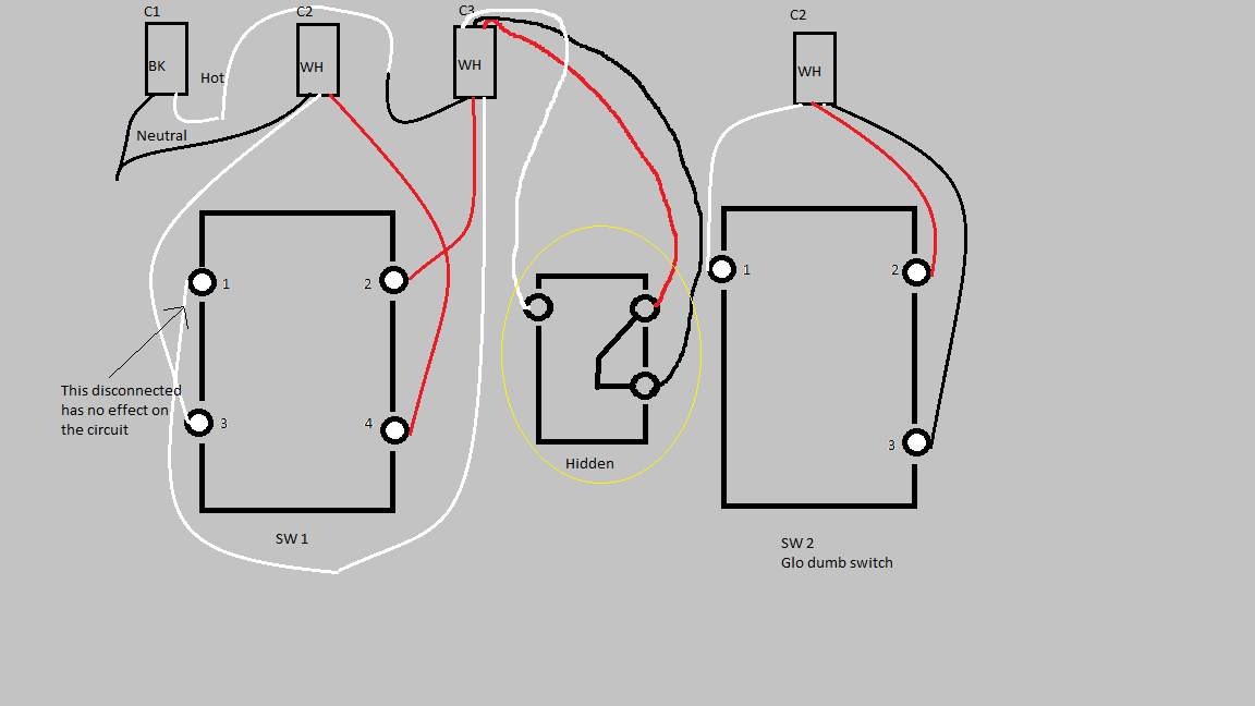
The hot/white from C-1 is effectively connected directly to #2 on SW1. Disconnecting the C-3 white wire from SW1 has no effect in any switch position, any readings are from SW1 terminal 4. I do not know if the 119 vac on C-1 white is line or load. It is constant and not switched.
The yellow "hidden" is an unknown black box. I don't know if it is an abandoned switch or just a splice from when the original electrician changed his mind. Can C- be both line and load?

