I made this video for another purpose (this is pretty basic automation stuff described here), but I thought it may be of interest to someone here anyway. When I was researching the Zen54 0-10V module I didn't really see many real-world examples in the forums.,. so figured it may help someone else in the future, maybe spark some ideas, help your project along.
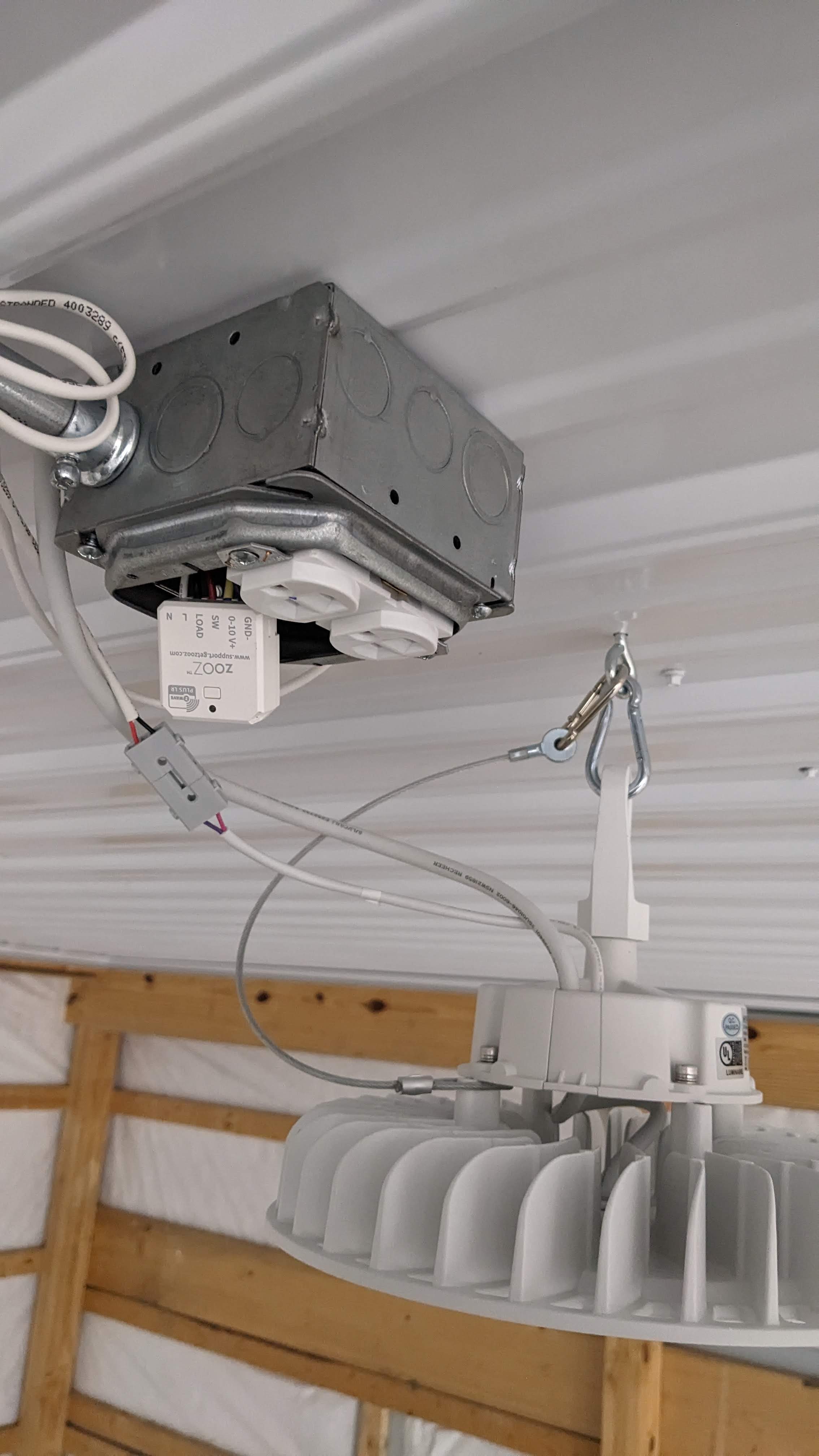
All circuits, the wall scene controller (and any future wall controls), the outlets on the ceiling, are all powered constantly. No switched legs or 0-10V are run (from wall) to the lights. Dimming is done via Zen54's installed at each receptacle box. This module switches power to 1/2 of the duplex receptacle (tie is broken). The other half is powered constantly for future use. Plastic outlet cover plates are used to ensure the wireless signal has a fighting chance in/out of the boxes.
Lights are commanded via the scene controller::button controller app/rule machine.
The dimming modules, low voltage connectors/wiring, and scene controllers only added minimal cost to the project (relative,... and Black Friday sales)
I originally considered running the LV 0-10 lines down to a junction box, however it's good that I installed them at the outlets - I discovered even at 0% the lights would not turn off completely, so the Zen54's switched output had to be utilized.
I have not bothered checked to see what the actual voltage output of the modules ended up being; it works, I just needed lighting!
Future automation tinkering may have to involve mmWave and light tracking.
One thing that would have made this immensely easier was if the module could be externally mounted on a box, with external LV connector. Something like a Rectorseal surge protector: has a threaded portion that allows it to secure outside a box with wires leading inside. This would allow you to keep HV and LV separate, and the module outside (for wireless sake in a metal box)
Things get muddy with the US NEC with respect to mixing LV and HV in a box, as related to class I and II supplies/circuits/wiring.
FWIW
In most (nearly all) commercial LED lighting the power supply controls the current into the LED's. Where the 12V strips you purchase on ebay every 2 or 3 LED's have a resistor to limit the current.
Current Control
Postiive:
all the individual LEDs vary linearly with current so dimming can be done by the controller.
Except for the quality of the components a current controller costs the same as a voltage controller.
neg:
If one LED fails (open) the whole string fails. If one fails (short) only the one LED is out.
Voltages can be quite high for long strips of LEDs. Easily in the 50 volt range.
Current controlled LED strips are not common and usually more costly.
LED strips are almost exclusively a shade of white.
Voltage controlled LED strips:
Positive:
Usually 12V, power supplies are nearly everywhere + Automotive are ~ 12V
12V and 24V LED strips are low cost and very common.
LED strips come in different colors.
Neg:
to dim the voltage controlled strips one needs a separate (from the PS) PWM circuit.