It showed up as a child device, possibly the updated code helped.
As always thanks,
It showed up as a child device, possibly the updated code helped.
As always thanks,
Please give it a day or so to run before you use the numbers which are related to the GAS reading. This is not exactly an AI. But, BOSCH does some machine learning to generate the IAQ. The value after it started will not be dependable.
I will be going out of on vacation on June 19th. If you need another one, please let me know before the 19th.
thanks for making this available to us. Is there an stl available to print a case for it? thanks again.
Hi @alexm, I do not have stl file for it. They are a 2 pieces PCB stacked one on another. It will be hard to make case based on the STL files. It is probably better to take approximate measurement and build a case for it.
I do have concern about cases. The module that I make is not a sleepy Zigbee end device. It is a zigbee repeater. It will never sleep. The MCU generate a very small heat that dissipated without any problem. If you case them, the heat cannot escape which will make the environment sensor reading a problem. I am aware that some member who use my sensor case them. I do not have any issue with that. However, my personal recommendation is not to use a case.
If you need to protect the sensor from extreme weather, coating the module with conformant coat or nail polish is something that I personally do.
The BME680 cannot be coated in any case.
Thanks
Iman
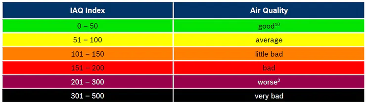
If you are looking for a threshold value for automation, here is what I got from BOSCH web site.
The BOSCH proprietary software seems to learn your room continuously. It attempts to score the IAQ between 25 to 500 based on the best and the worst gas reading within a time window. I do not know how complex this proprietary algorithm.
I use the staticIQA (not IAQ). I start my air circulation when staticIAQ reach above 125. It is really hard to hit IAQ 50 or less in my house. It is probably my house is sealed reasonably well. There is an advantage if you have home like this. The sensor can detect room occupancy. As we breath CO2, the IAQ will increase over time as the room is occupied. I am able to catch this form the sensor. But, I warn that this is probably not a replacement for your PIR sensor. It is rather slow. But, it can confirm that my room is occupied. Based on the IAQ value, you may estimate the number of occupancy although it is not precise. The IAQ will be at different level when you have one person vs 10 people in the room.
How do I do a factory reset on these devices? I saw it someplace but can't find it again...
Thanks,
Pretty easy to find with a search of this topic:
Can you hook up a temp probe to this? I need to measure lake temperature.
Thanks
Mike
@mjruotolo, yes... the modules can be fitted with external temperature probe. There is a couple option to go with this. One of them is using Arduino like below.
Another way is using the analog input of this sensor with K-type thermocouple module like below.
I helped a couple members here who happen to measure lake temperature. I think the ds18b20 is more agile since it can be wired with a long wire. When you narrow down your choice, I can help you with it.
I have both of these the one that is in the lake is using the DS18D20, I have the lake temp forwarded to several others via text and it is announced by Alexa in the morning.
If I could figure out how to do it I would also use this module with this water level sensor, Water Level Sensors
Hi Everyone,
It has been a while since I have made an update here. This project is still going. I am still spending time to improve the Environment Sensor. If you follow this project, the latest sensor that we are supporting is BME680. BME680 add gas sensing on top of the Temperature, Humidity and Pressure. It is nice to know some aspect of the room in term of VOC, CO2 level as they can be dangerous.
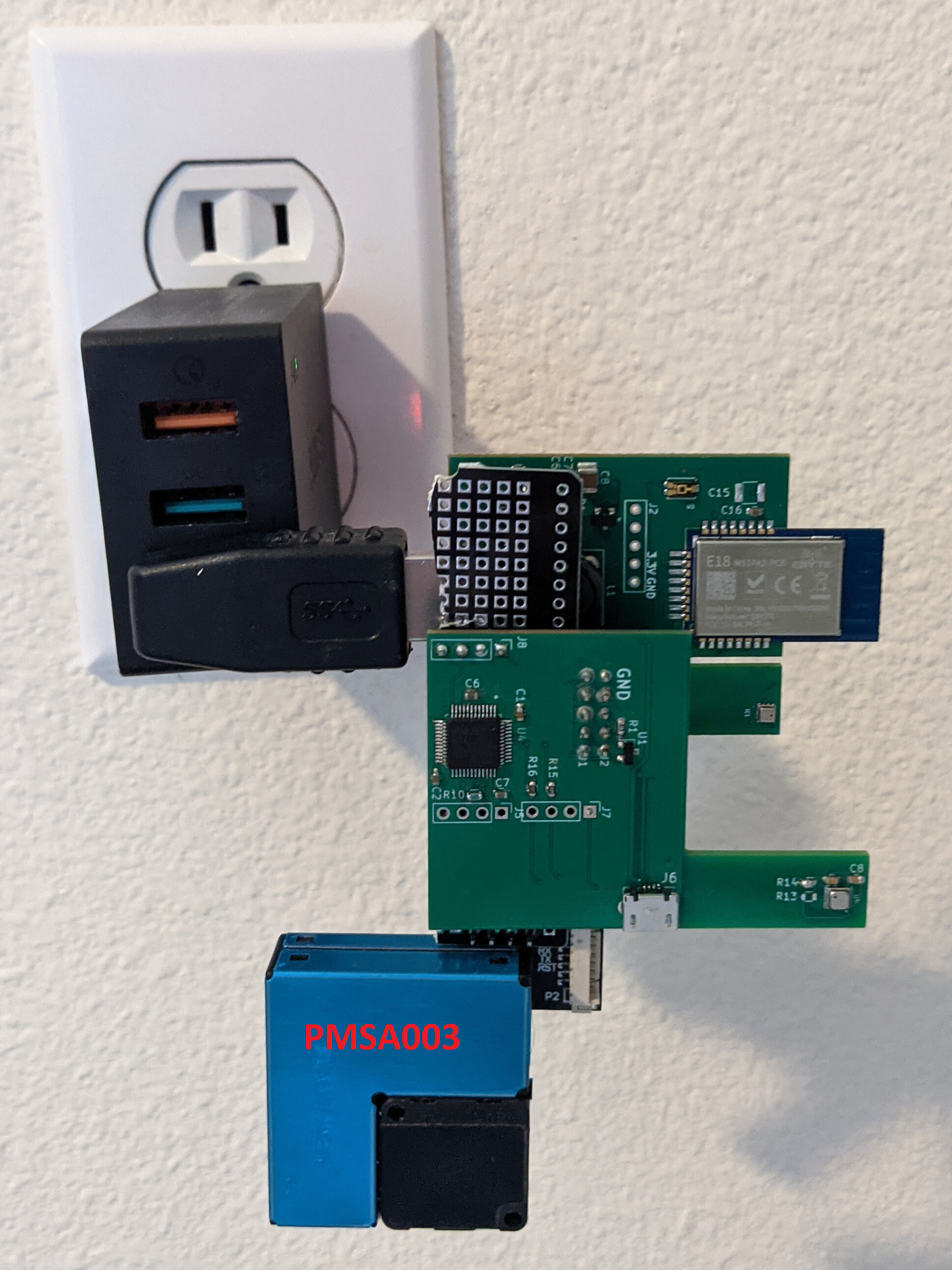
Today, I am adding support to PMSA003 sensor. PMSA003 is a low cost dust sensor (or, is likely a small particle sensor). Monitoring small particle is something that I am interested on. Some of these particles may be unhealthy.
Supporting the BME680 and PMSA003 showcase the serial expansion capability of the Environment sensor. The environment sensor comes with UART ports where you can add Arduino and use the Environment sensor similar to ThingShield.
Here is a photo of my prototype unit.
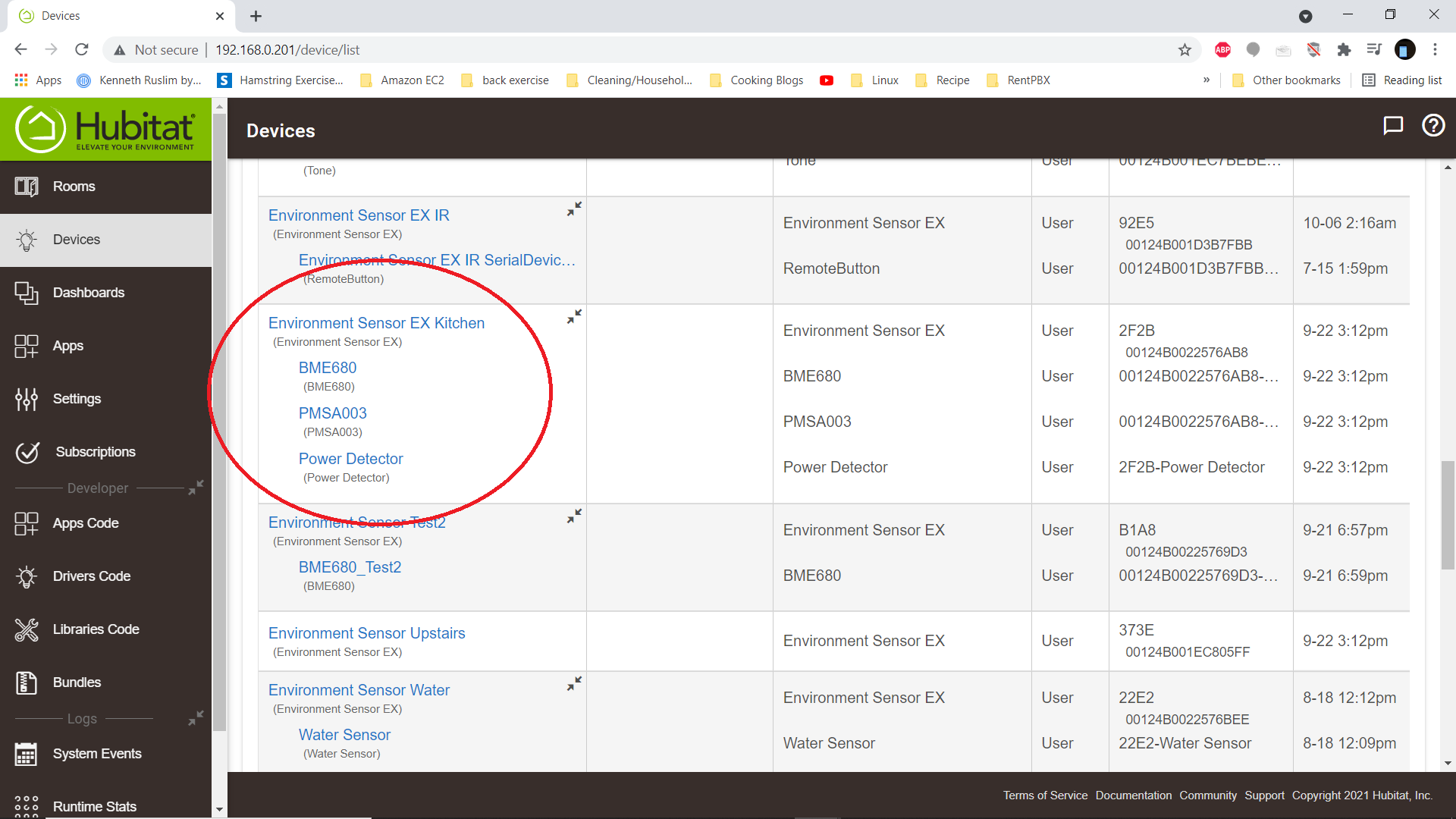
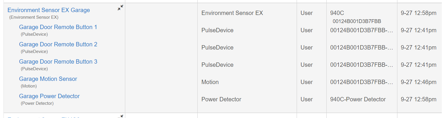
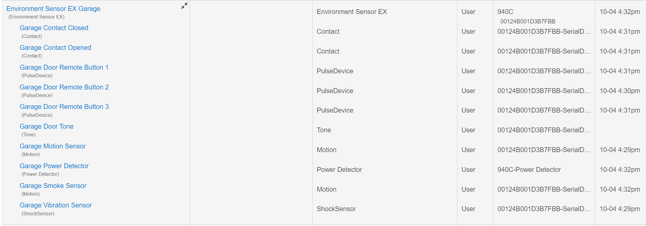
The sensor above will show up like below in the Hubitat.
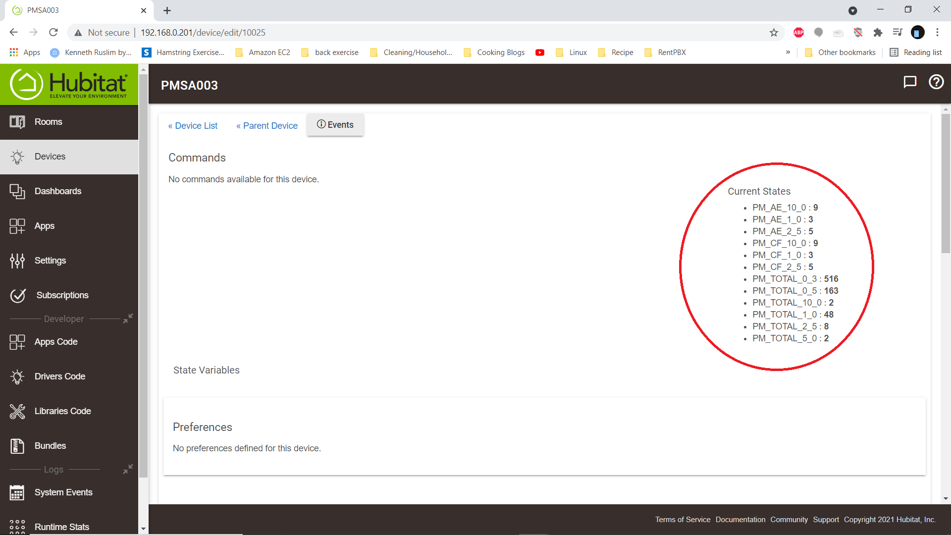
I am not going to bored you with the Power Detector and BME680 devices as the detail for those are here. The PMSA003 readings will show up like below.
I plan to build and design PCB which will integrate the PMSA003 in some future time as the project goes on. I am making these variants of Environment Sensor as a roadmap of what we can do with it. As pictured, I have a single module monitoring whether my room has power. I can open and close my curtain based light reading, I can control my HVAC based on current temperature, humidity, air quality of my room. It is a Zigbee repeater as well to help me build my Zigbee network. And now, I can do more knowing whether I have dusty room.
Anyway, I want to thank everyone here for their support. I am able to do these projects because of the help of many of you by purchasing my released Environment Sensor in Ebay.
Thanks
Iman
Like many of us with MYQ garage door, I am affected by changes in their cloud that caused the MYQ integration stopped working.
I found a solution inspired by some member here to take MQY integration local like the following thread.
If you have time to go through the above thread, you will find lot of good and detailed information to solve the issue. I personally picked a solution that simulate button press using an existing remote. A switch device in hubitat will be created to represent the button. Using this switch device, you can follow the thread there that there are sets of applications that you can use to complete the solution that give you a garage door device.
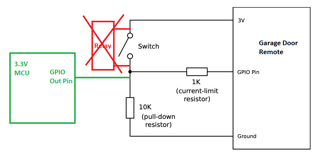
What is unique with what I am doing with the switch is that I want to eliminate the need for a relay. Most of the solution presented in the above thread require a dry contact relay. Eliminating the relay is possible since the button on the remote is a typical GPIO mechanism. Based on my understanding, the button roughly is as follow.
The idea is just connect a GPIO output from a 3.3V MCU straight to the button GPIO pin of a remote. This should have the same effect as shorting the switch to the 3V source.
Another twist that I did is to remove the battery and power the garage door remote from the 3.3V source of the MCU. The voltage difference is so small It would not break the garage door.
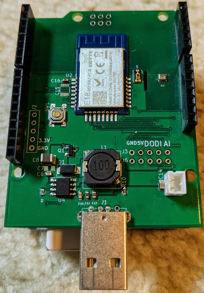
Here a prototype using the Environment Sensor digital output to test the ide. You will see that there are only 3 wires needed for power and a single gpio.

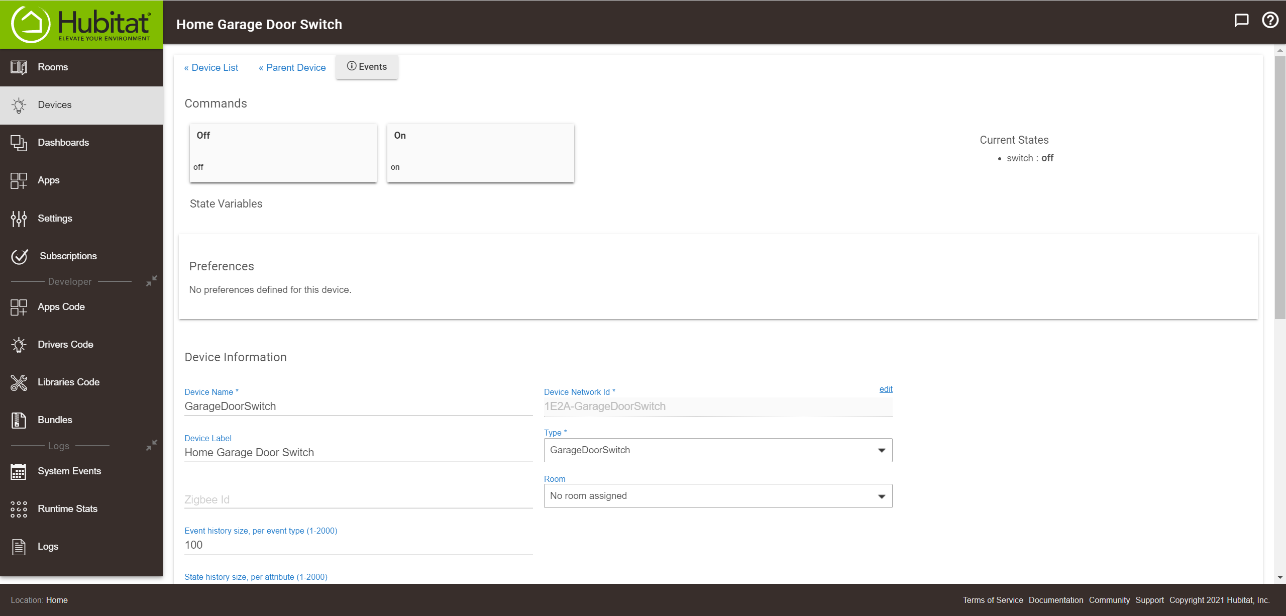
The switch will look like below.
Just FYI, this is just prototype to share my idea. My plan is to use an Arduino as expansion to the environment sensor. One of the reason for this is that the remote control has 3 buttons that I would like to take advantage while the Environment sensor only have one. With Arduino, I can have access to a lot more GPIO. There is also technical reason where I would like to have the Arduino to handle the button toggling rather than involving the hub. I also have plan to integrate additional sensors that would make sense for our garage door.
At this point, I just want to present an alternative which may be simpler for some of us.
Thanks
Iman
It resembles the ISS! 
I just want to update everyone here that over the weekend moved the garage door solution using Arduino to support 3 buttons.
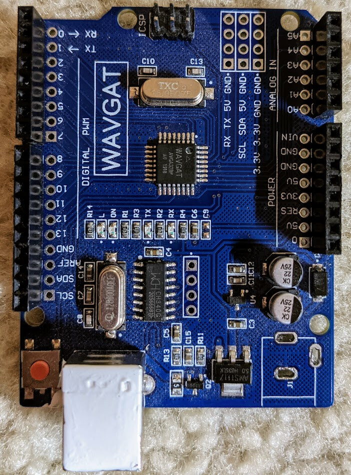
In the past, I have made an Environment Sensor that is in the form of Arduino UNO shield.
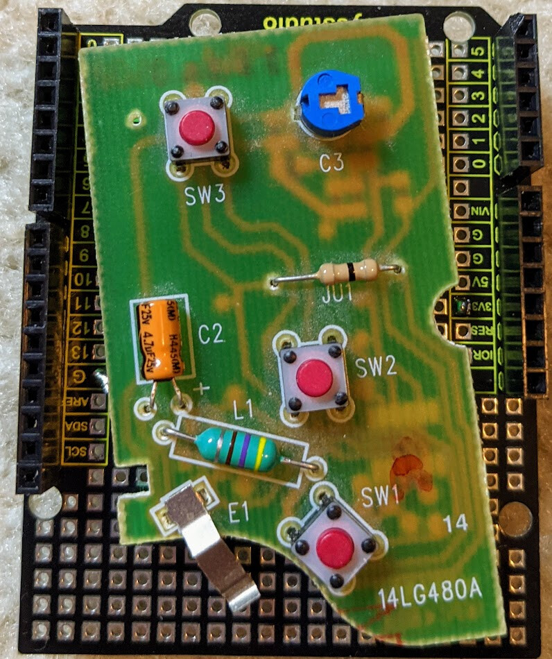
I soldered an Garage door remote to Arduino shield prototype board.
The last parts needed is an Arduino UNO. Just FYI, I am using a clone with WAVGAT brand. This looked like Arduino UNO R3. It is not exactly the same. The WAVGAT run on 3.3V (not 5V).
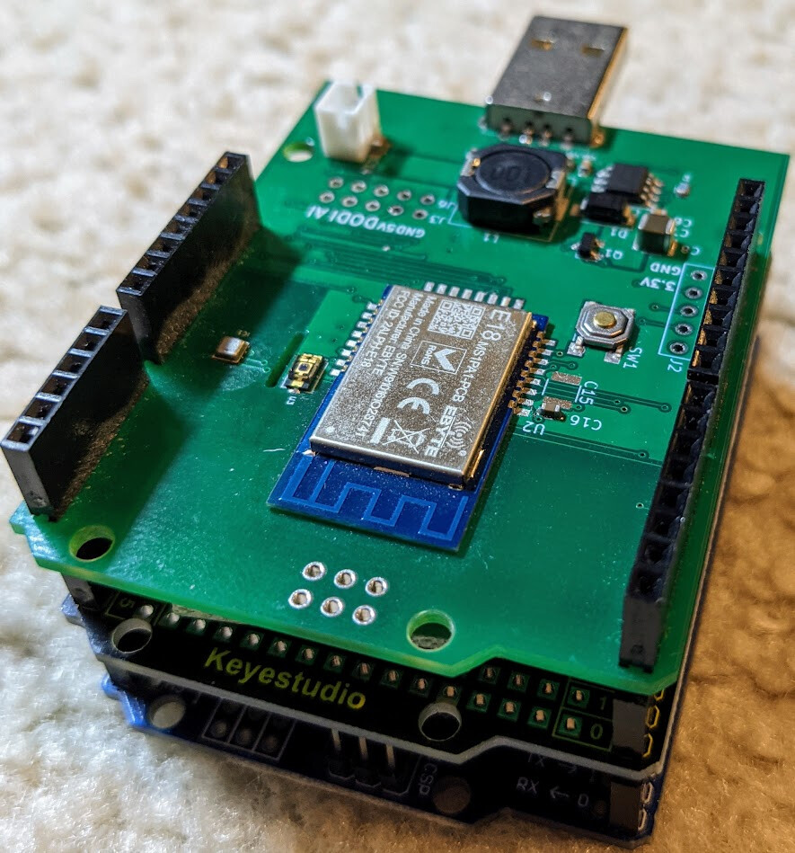
Here is how it look like stacked together.
Here is a short video clicking the button 3.

The Arduino is overkill just to help pressing the button. There are many GPIO ports that is still free to use. I am also planning to add more and more sensor to it. I have a motion sensor connected to it and AC power detection to it.
Thanks
Iman
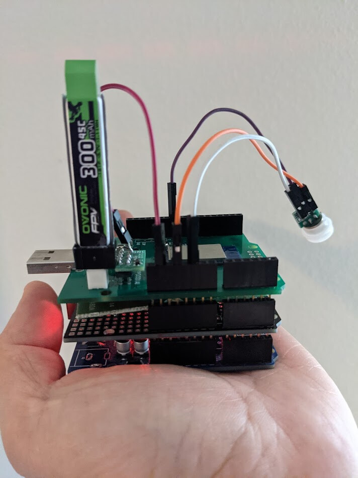
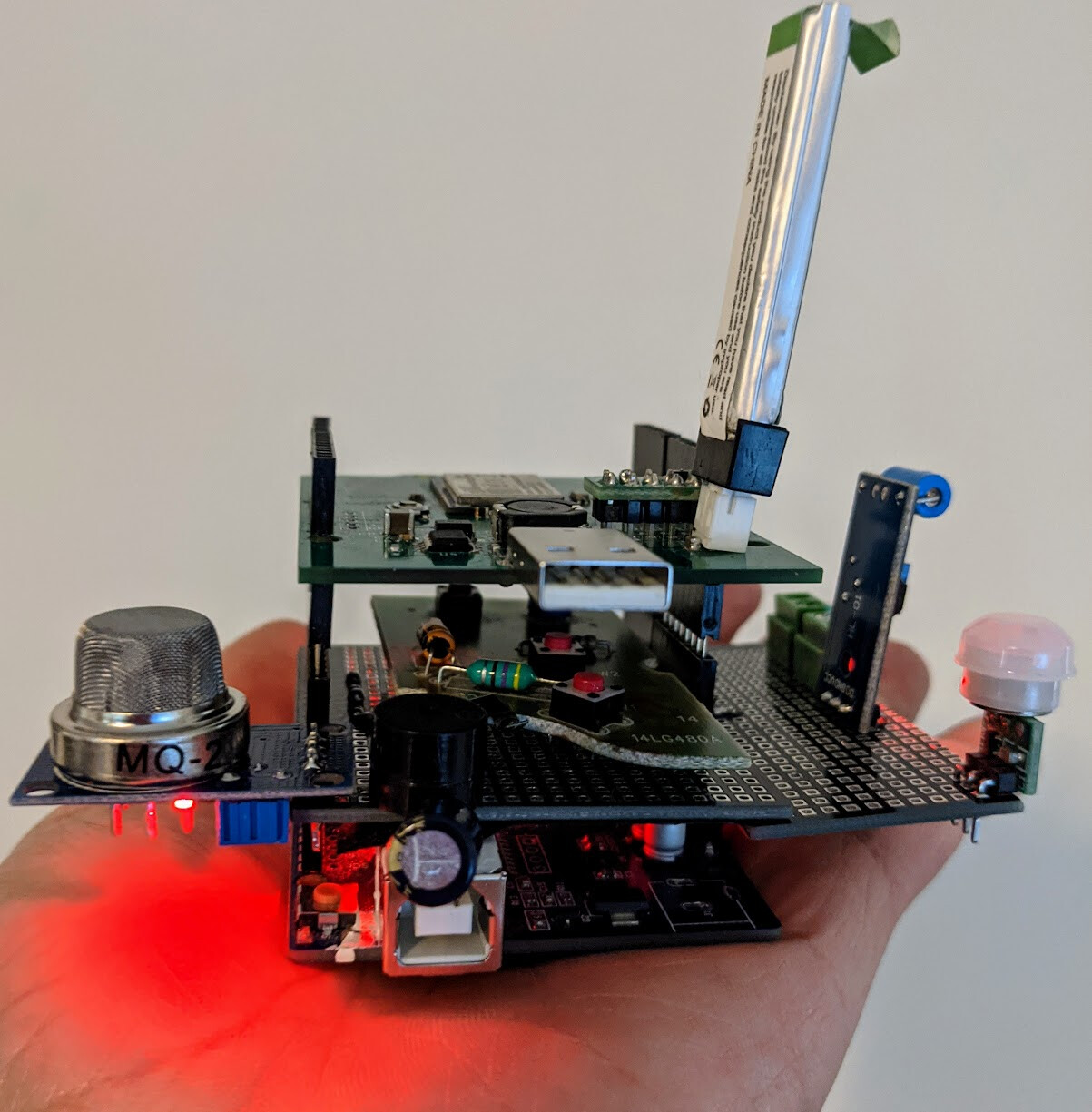
I just add a few more sensors. I think they will be the final set of device/sensors that I have integrated. I will be installing it this coming weekend in my garage. Here are the final set of sensors. I just add a sets sensor/device to address some safety aspect of the garage door. I added the smoke sensor and a beeper. It is inspired by the work done @manuelangelrivera with his garage door.
All of the above fit in the palm of your hand.
That thing is a monster lol
You need to 3d build a case for it
I have 3d printer. It is a bad one. In combination with my poor mechanical skill, I never really gotten anything worth out of my 3d printer.
My plan for this specific project is to let it install bare for now. I know that the Environment Sensor need to have exposure to the air. The light sensor need a clear enclosure.
Eventually, YES, I would like to have a case. Some of those clear food container case may have to do. I have not find any project enclosure that is clear case. If anyone have suggestion, please let me know. This project need the environment exposure. Some sensors really need air flow.
Just an update... I have installed my garage door controller. While setting up the contact sensors, I have another idea to use it as rotary encoder instead of detecting the just the "fully" open and close position.
I posted the demo on another thread. If you missed the demo, Here it is.

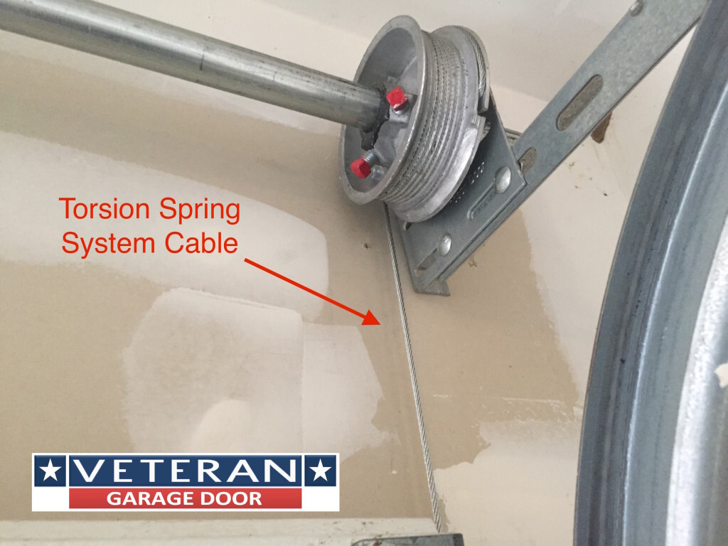
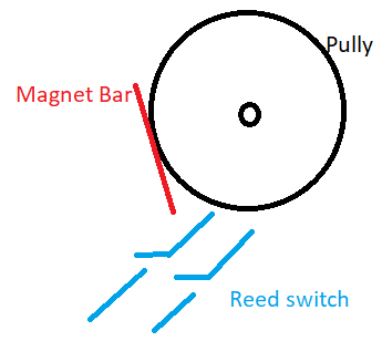
I think I would add a detail on how I did this here. The technique is not new. I uses a couple reed switch with a magnet. I install the magnet on my GD pully like below.
 .
.
As the magnet approach the reed switch, I am able to count the position of the garage door. I do need to start from a known position. This is easy to do. I uses fully closed position as 0. The 2 reed switches are needed because I want to know the direction. As the magnet approach the switch, the first switch that is closed first will tell me the direction. The basic principal is as simple as detecting which of the 2 switch closed first and deduce from that the direction of the move. Also, as the event happen, I count up or down depending on the direction. That is pretty much it.
FYI, here is the location of the pully that I use.
I was worried prior to testing this about the accuracy of the encoder. It really depend on the sequence of the contacts closing and opening to get it right. In the end. I am surprised how well it works. It is also have huge tolerance. The installation of the reed switches do not have to be very precise. The magnet does not need to be aligned precisely. My thinking is that the rotation is very slow. Therefore, the encoder does have a lot of flexibility.
I started looking for MYQ replacement. I think with the other stuff that I can fit on the board, I got much more than what MYQ can give.
Brilliant! And I can use this whereas my other ideas have hit major hurdles. Thanks, Iman.
Download the Hubitat app