Tuya is terrible. Hubitat and Home Assistant is not. At the beginning of this project, I only had Hubitat. I tried to get the fan working with Tuya Cloud integration and the ESPHome driver for Hubitat, but both are half-finished and don’t support combined devices like this very well.
So, this how-to will talk you through building a Home Assistant (HA) machine, installing ESPHome, flashing the chip in the fan, configuring it in HA and then synchronising HA to Hubitat.
In addition to the fan itself you will need:
- A PC for Home Assistant to run on 24/7 - which you could run in the Virtual Machine, or a Raspberry Pi – it only needs network access, but I used an old Dell mini-PC.
- A Windows PC to flash the firmware – you could potentially do it with the UART directly connected to the HA machine, but that wasn’t what I did.
- A serial UART that does 3.3V signalling. Make sure the switch/jumper is set to 3.3V. I used this one https://www.jaycar.com.au/duinotech-arduino-compatible-usb-to-serial-adaptor/p/XC4464
- A mini-USB cable for the UART
- A steady 3.3V power supply. The 3.3V or 5V from a USB UART isn’t usually powerful enough to run the module reliably. I used this one https://www.jaycar.com.au/0-36vdc-0-5a-slimline-80w-lab-power-supply/p/MP3842
- Wire-wrap wire
- The things below typically come in a Arduino or ESP discovery kit, so maybe you can buy one of them, like this https://www.jaycar.com.au/duinotech-arduino-compatible-uno-starter-kit/p/XC3902
- Breadboard
- Pins to solder onto the wire-wrap wire so it can push into the breadboard.
- Some breadboard jumpers
- Tools such as a fine tip soldering iron, screwdrivers, cutters, magnifying workstation, etc
Install Home Assistant
I installed the x86 version on an old Dell mini PC with these instructions - Generic x86-64 - Home Assistant
Install ESPHome
I followed these instructions - Getting Started with ESPHome and Home Assistant — ESPHome
Make some firmware
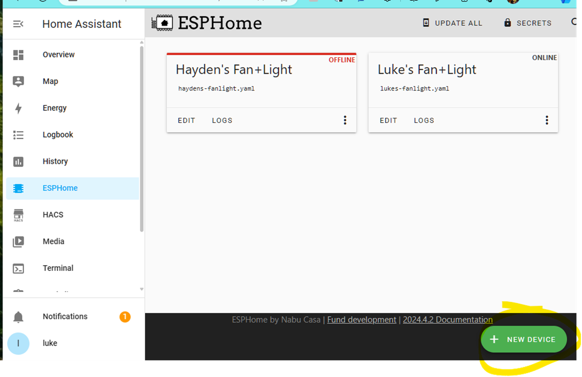
- In the ESPHome tab click New Device in the bottom right.
- Rather than installing directly from the computer running HA we will build firmware and install it using a Windows PC. Click Continue.

- Name your device
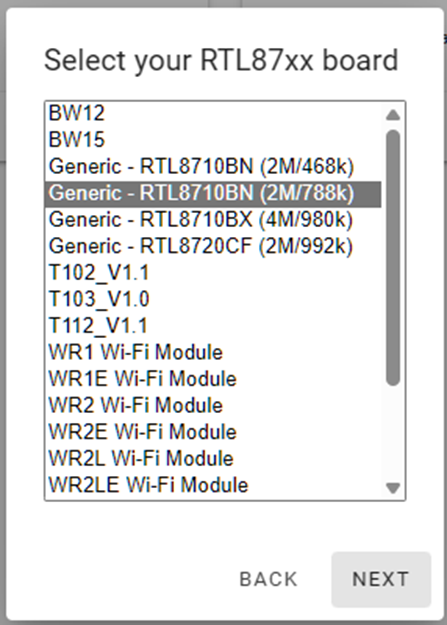
- On the Device Type screen select RTL87xx, then Generic – RTL8710BN (2M/788k)
- You don’t need the encryption key yet, so no need to take a copy, its just FYI. Click Install.
- We want to install it on another computer (not the one running HA), so select Manual Download.

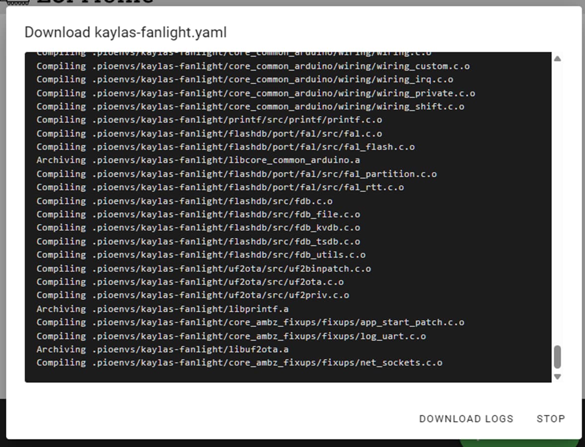
- ESPhome will build the firmware and then offer you the file to save.
- Choose UF2 Package
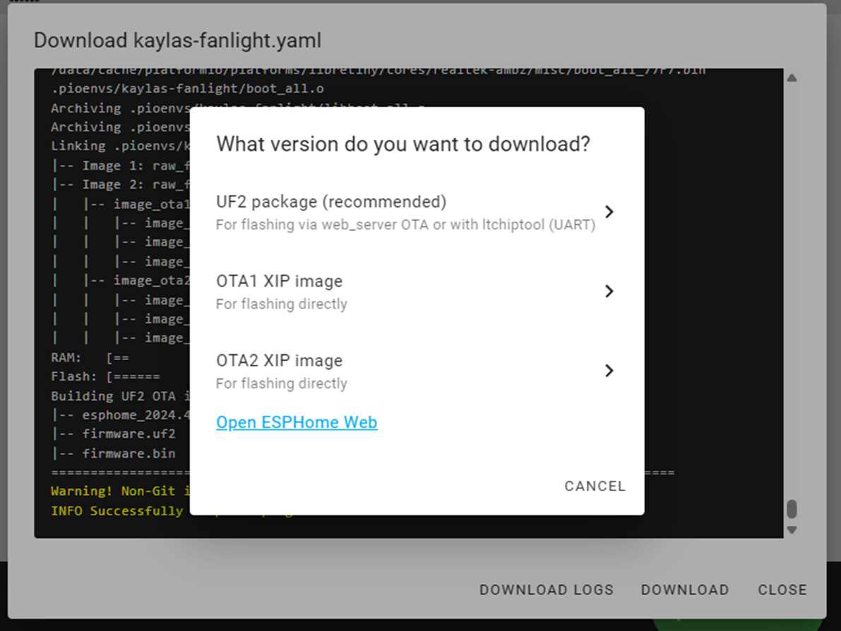
You now have a firmware image to flash into your device.
Flash the firmware image
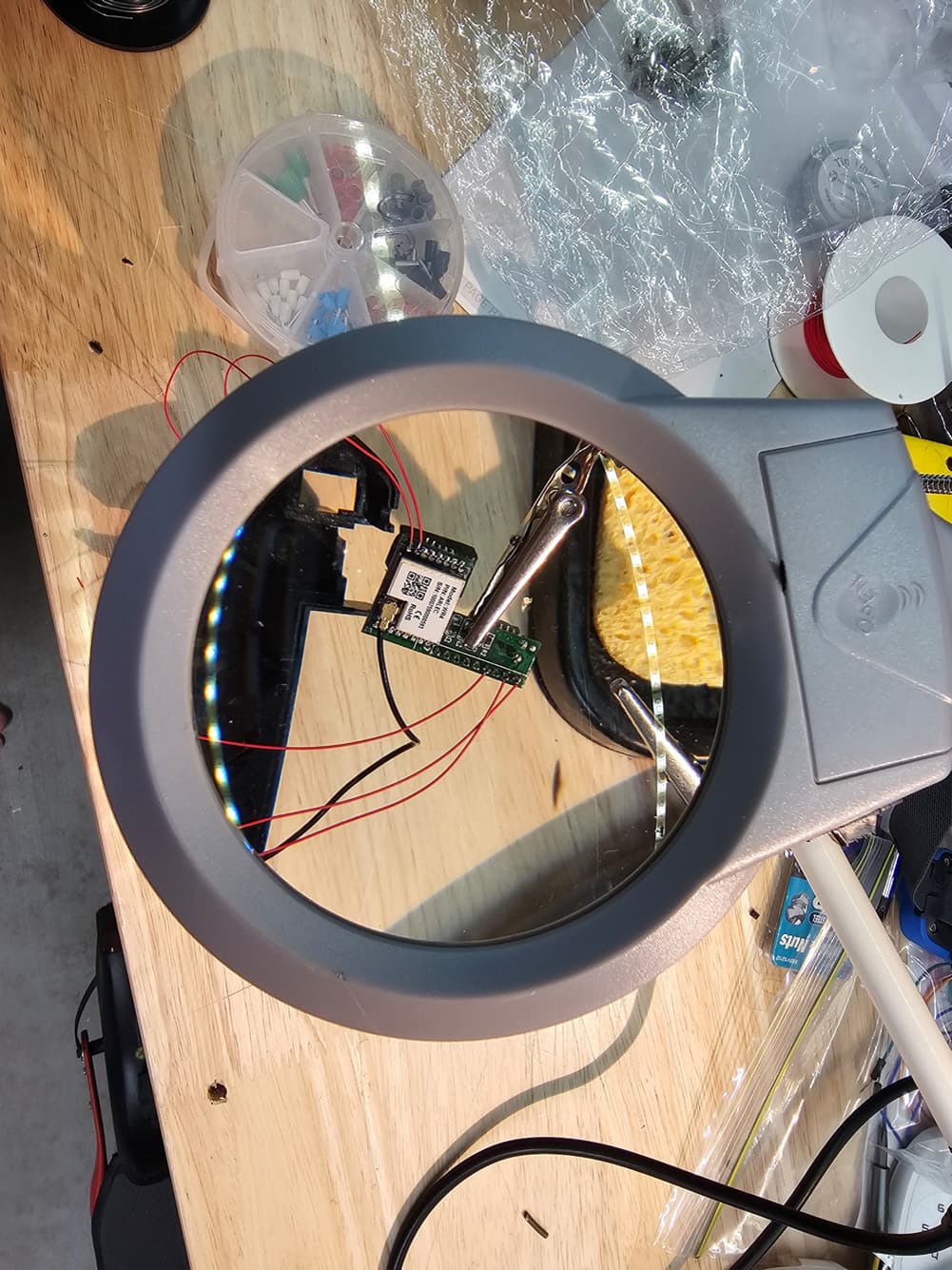
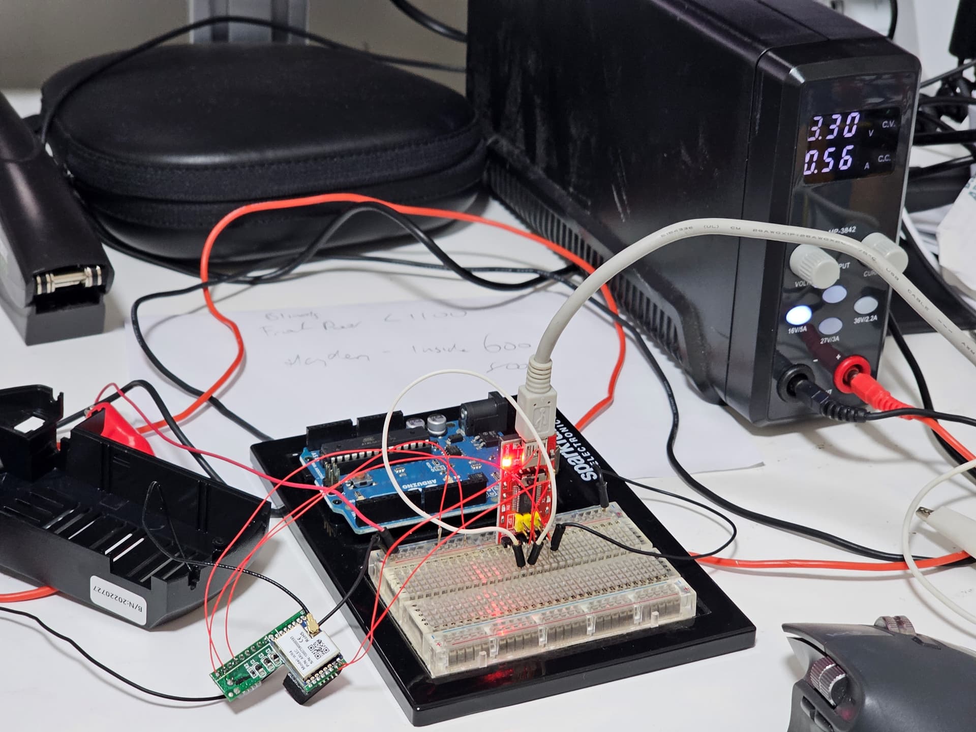
- Wire up the board to the UART and Power Supply as below:

This diagram came from projects:arlec_smart_fans:overview [Travis' Wiki] however it had a typo, which I have corrected in red.
- Open the fan controller module. Remove the WR4 PCB from the main board and remove the block of foam from the pins. Be careful to not jerk the Wi-Fi antenna cable as the unit comes apart.
The unit is full of 240V when its live, and possibly it will still be charged with high voltage DC for several minutes after power is removed. Be careful.
- Solder ~10cm lengths of wire-wrap wire to the respective pins of the PCB. A magnifying workstation helps a lot here, particularly if your eyes are old like mine.
- Solder pins onto the other end of the wire-wrap wire to push into the breadboard.
- Assemble the build per the circuit diagram. Make sure the Wi-fi antenna is connected.
- Download ltchiptool from Releases · libretiny-eu/ltchiptool · GitHub into a working folder. Copy the firmware image from above into the same folder.
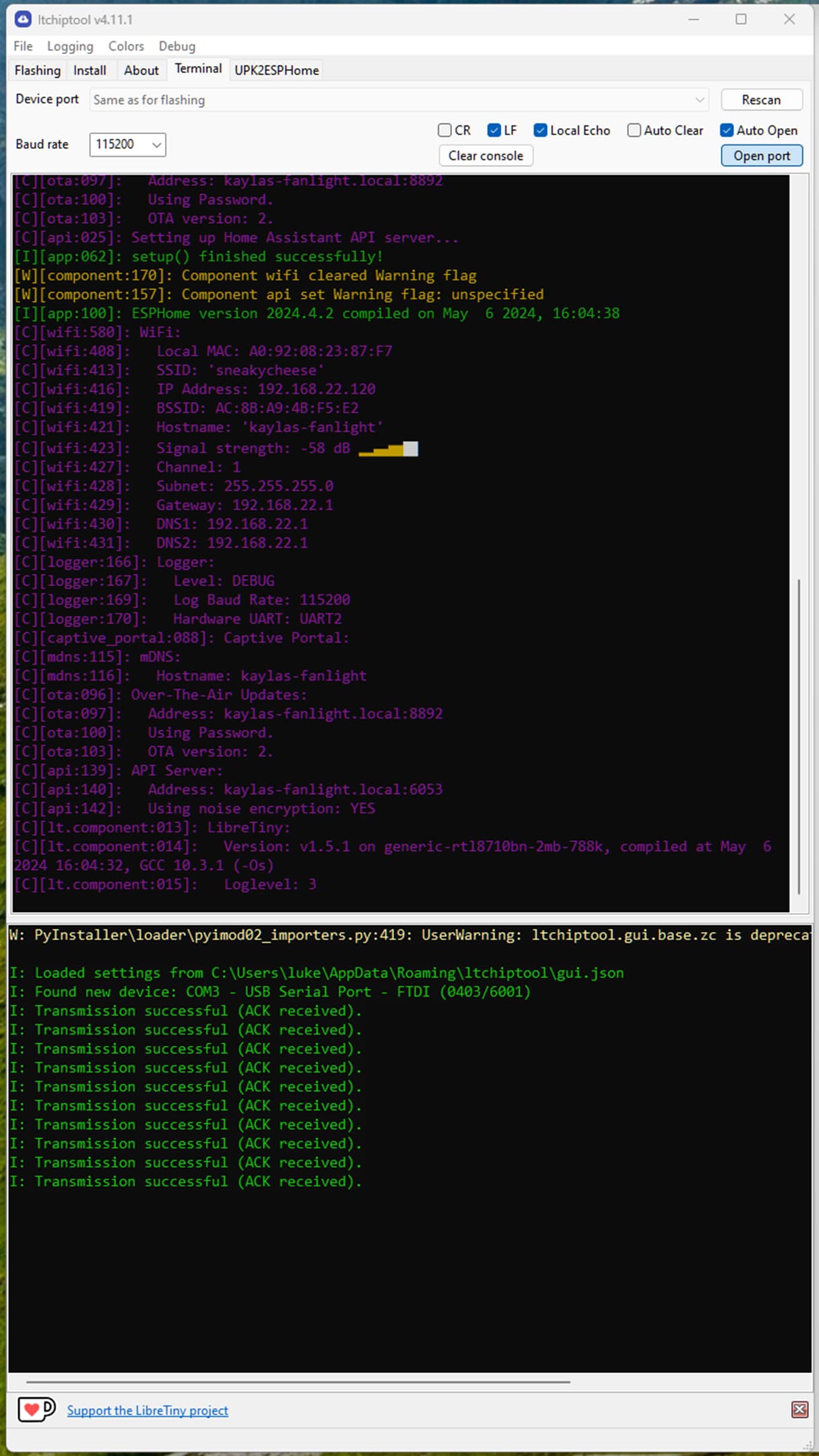
- Open ltchiptool and go to the terminal tab. Set the baud rate to 115200 and click Open Port. Power on the power supply and you should see the boot loader waiting for instructions:

If not check your connections and try again.
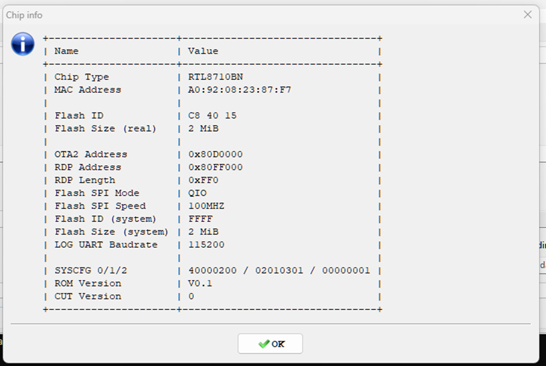
- Click on the Flashing tab, pick Realtek AmebaZ and, Get chip info and click Start, you should get some info from the chip.
- Backup the firmware by selecting Read flash and clicking Start. You should get a 2mb .bin file saved in the working folder with the Tuya firmware in it.
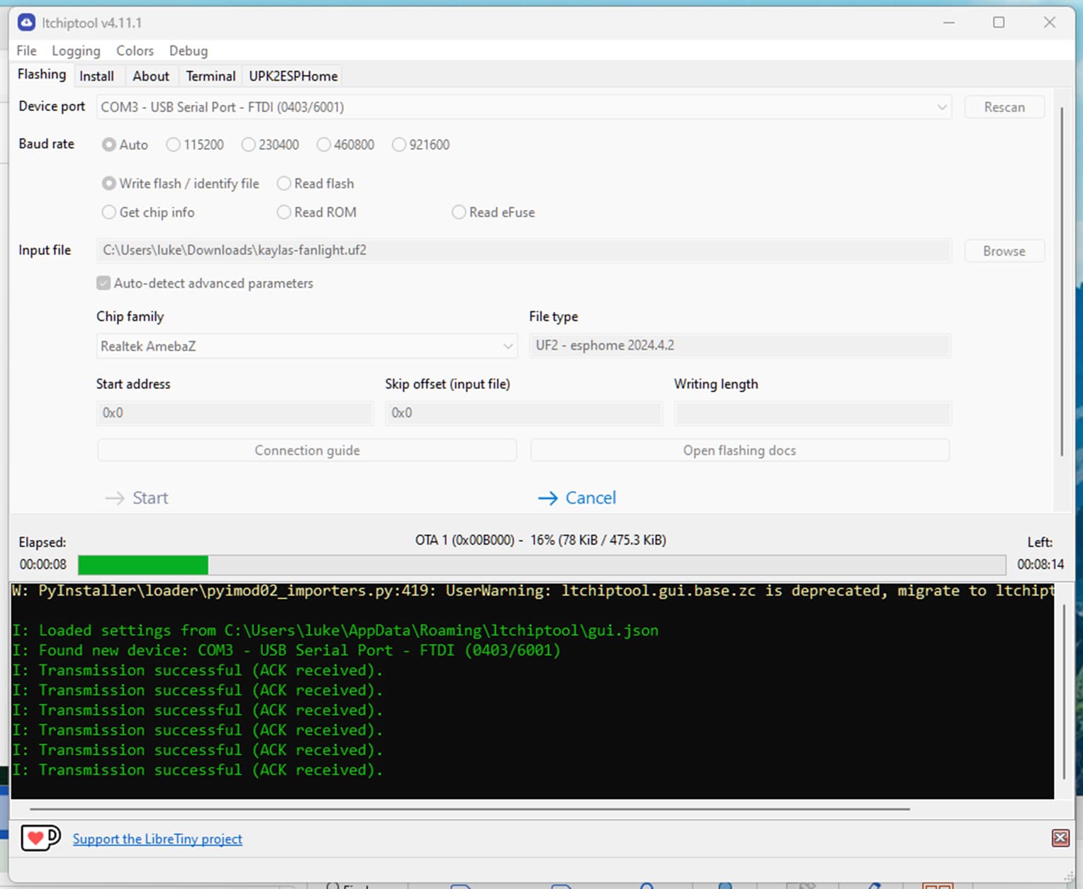
- Write the firmware you saved in the last section to the chip by selecting Write flash and clicking Start.
Once the firmware is written you’ll see it boot up in the Terminal tab:
Customise the firmware to talk to the Arlec Fan
Currently your WR4 module is talking to ESPHome as shown by it being ONLINE:

Now we can customise the ESPHome configuration so it talks to the MCU (controller) of the fan and light.
- Click the EDIT button and append the following configuration to the configuration YAML file:
uart:
  rx_pin: GPIO18
  tx_pin: GPIO23
  baud_rate: 9600  # This is a common baud rate for Tuya devices

# Configure the Tuya component and ignore the datapoints not used in this configuration (e.g. sleep timer)
tuya:
  ignore_mcu_update_on_datapoints:
    - 102
    - 103

# Fan configuration
fan:
  - platform: tuya
    name: "Ceiling Fan"
    id: ceiling_fan
    switch_datapoint: 1
    speed_datapoint: 3
    direction_datapoint: 4
    speed_count: 6

# Light configuration
light:
  - platform: tuya
    name: "Light"
    id: ceiling_fan_light
    switch_datapoint: 9
    dimmer_datapoint: 10
    min_value: 0
    max_value: 100
    color_temperature_datapoint: 11
    color_temperature_max_value: 100
    color_temperature_invert: false
    cold_white_color_temperature: 6493 K
    warm_white_color_temperature: 4065 K
    default_transition_length: 0s
- Click SAVE then INSTALL. We can now install updates Over the Air (OTA) so click Wirelessly:

- ESPHome will compile and push the new firmware to the device over wifi and reboot it. The device will now hang however as we still have the RXD and DTR lines on the UART linked which boots the chip into the bootloader.
- Remove RDX-DTR the link and power cycle the WR4.
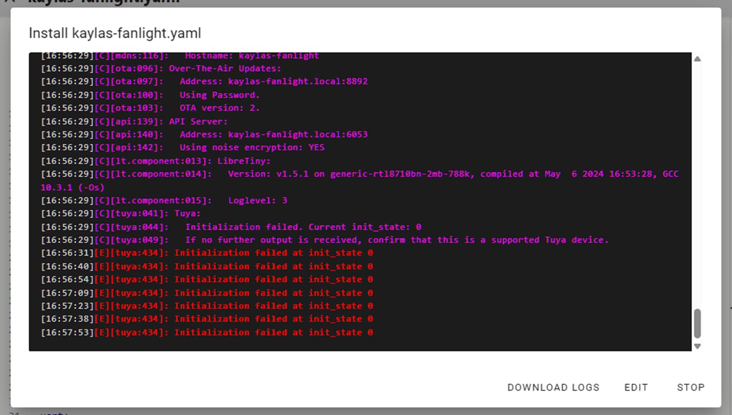
- You’ll see the WR4 boot back up in both the ltchiptool terminal and ESPhome. It will connect to wi-fi and then repeat errors communicating with the Tuya MCU as its not connected.
- Click STOP and close the configuration window in ESPHome.
- You can now unsolder the wire-wrap wires and re-assemble the WR4 PCB back into the fan controller. Note that the MCU socket closest to the antenna should be empty as there isn’t a matching pin on the WR4 PCB.
- Put the casing back together, being careful to keep the wi-fi antenna connected and not tangled up inside the case. Re-attach the wiring harness to the module and install the fan as per the instructions.
- When you power up the assembled fan you should see any button presses on the remote come through in the log as the fan changes speed, etc.
Configure the fan device in Home Assistant
- Make sure the fan is powered up and connected to Wi-fi. You should see it connected and logging to ESPHome.
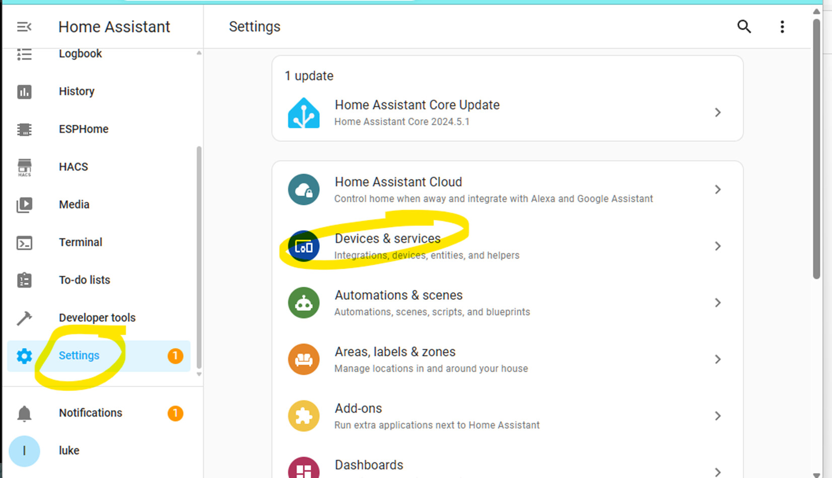
- In Home Assistant click Settings, Devices & services:
- Scoll down to ESPhome and click the arrow:
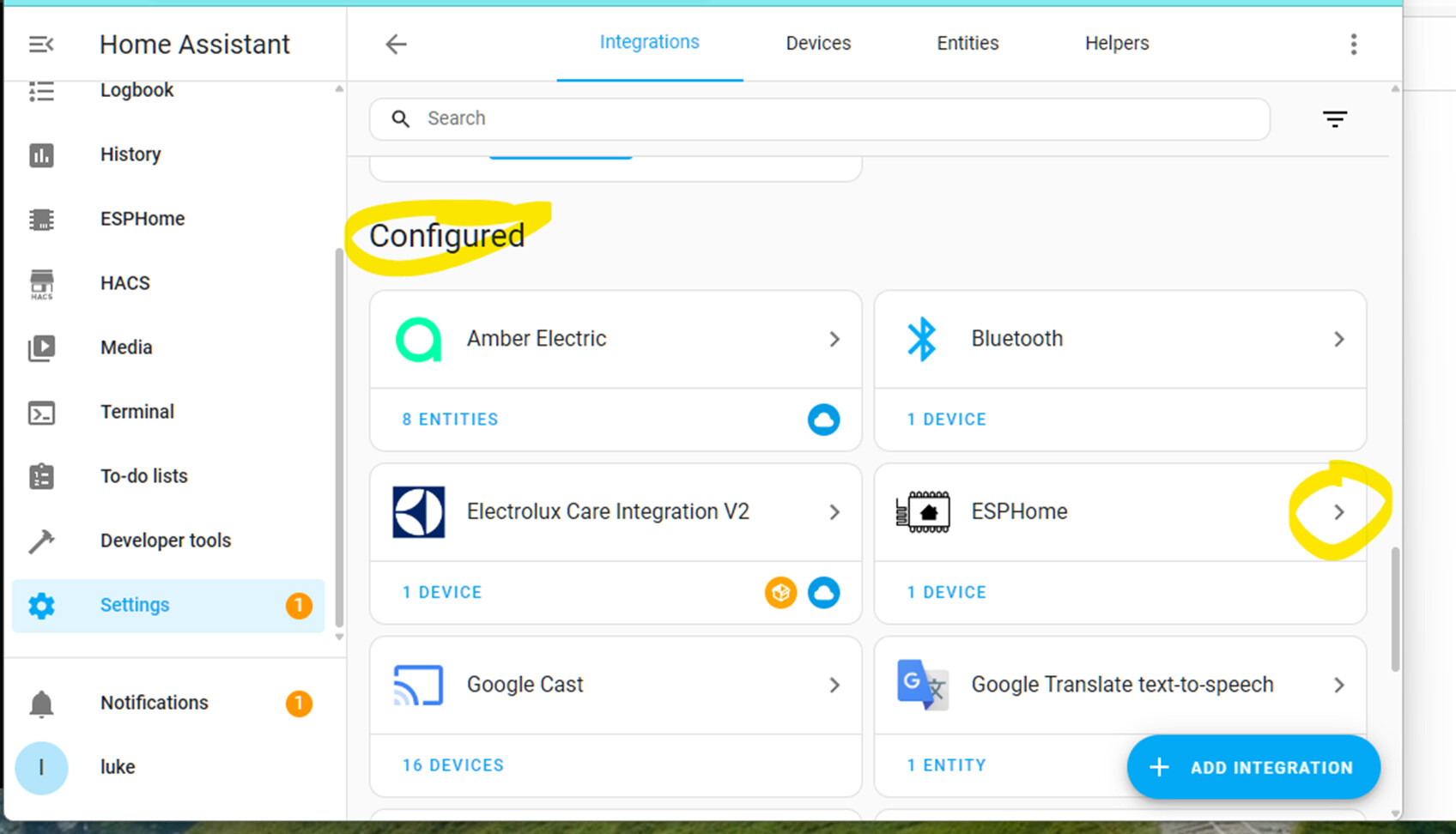
- Click ADD DEVICE and pick the new device from the list. Confirm you’s like ESPHome to add the device to HA. Click SUBMIT.
- Confirm which area you’d like the device in and click FINISH.

- You should now see a live connection between the fan and light, and the virtual child devices in HA.

Sync the HA device to Hubitat
- Instal Home Assistant Device Bridge (HADB) into Hubitat. I recommend using Hubitat Package Manager to do so. Details here - [RELEASE] Home Assistant Device Bridge (HADB)
- Once HADB is configured you can pick the fan and light devices in the app:

- One important trick is that the HA devices won’t be installed as children of the HADB device until you make them do something in HA. So go into the HA GUI and toggle the fan and light switch on and off.
All feedback welcome!

