I've got a few Zooz Zen26s that I want to install in a 3 way setup with an existing switch. I've got a multimeter and I know how to use it. I just specifically am not sure how to figure out which way to wire the switch. I'm sure there is some systematic way of testing all the wires to figure out what's what. Does anyone know of a good video or tutorial for this?
The Zooz store has wiring diagrams.
https://www.thesmartesthouse.com/collections/zooz/products/zooz-z-wave-plus-s2-on-off-wall-switch-zen26-with-simple-direct-3-way-4-way
Wiring codes require specific color wires for the ground (copper or Green), neutral (white), load (black), traveler (red).
Its usually not too complicated, however starting blind (aka not knowing how it is currently wired) can be a challenge for someone who has not done this before.
The first thing to do is to (with power off) pull out the existing switches (do not disconnect them).
Count the wires in the boxes, photos are good. The goal being to create a simple sketch of the current wiring, even if you can't tell what is going where, knowing the existing wires is usually a good first step. Note. Depending on the age of your home, there may or may not be a bare wire going to each device. You can ignore these for simplicity.
John
1 Like
I would use wire color as a clue only and in no way assume that they are correct. Although if there is a red wire, then I'd bet money that it is the traveler.
Start with what @JohnRob just posted. Use some logic such as if there is only one Romex that goes out the top of the box and its an overhead fixture, then it probably connects to the load. Again, just a clue, not a certainty.
At some point, you probably need to remove all wires from both switches except bare copper (after documenting how they were wired, and also with power off of course). Make sure the bare ends of the wire aren't touching each other or the box if not plastic. Turn power back on and carefully measure between each wire and ground. Get 120V potential between a pair? Then that wire is probably line.
If you think you know which is line and which is load, temporarily wire line to load and neutral to neutral (with power off), and see if the fixture lights when you turn power on. With a few experiments like this, you'll be able to match up with one of the wiring diagrams.
Be really careful about whether power is on or off. Check it twice and don't just assume just because you flipped a breaker that there is no power in the box. Use your multimeter and preferably a non-contact voltage tester too.
1 Like
This is exactly what I was looking for. I knew how to determine which wire is the line, but wasn't sure how to determine any others. It never occurred to me that I could simple connect line to other wires and see where the electricity goes. It'll require a lot of back and forth to the breaker, but should be fairly easy. Of course, I say that, which means I'll have some weird setup that doesn't make any sense to me.
my multimeter also has a NCV tester at the end. It's super handy. It's saved my bacon at least once too. I was wiring a new ceiling fan into my son's room. I had the old fan/light turned on so I could visibly see the power was cut when I flipped the breaker. I unscrewed the wall switches and pulled them out a little bit, but before touching any wires I used the NCV tester, and sure enough there was something still hot in the box. Turned out that the circuit that goes to the master bedroom also connects into this box somehow. I have a feeling that is probably against code, but I don't know.
Not exactly, In particular, if you connected line to neutral, that would not be a good thing.
Just giving another example of investigating with your multimeter .. if you have zero or near zero voltage between ground and a wire, then you know that wire is NOT line.
Regarding a hot circuit inside the same box, that wouldn't be common but not all that unusual either. I have a dual gang switch box with not only two different circuits in it, but on different phases. Which means there's 220V inside that box.
Just remember, the Ground and Neutral are NEVER switched. Don’t break their uninterrupted path to the breaker box.
I figured out 2 of my Zen26s and they are working great. Went to do the 3rd one and this is wired differently than the other 2 locations and I'm stuck.
Here are the wiring diagrams that come with the Zen26.
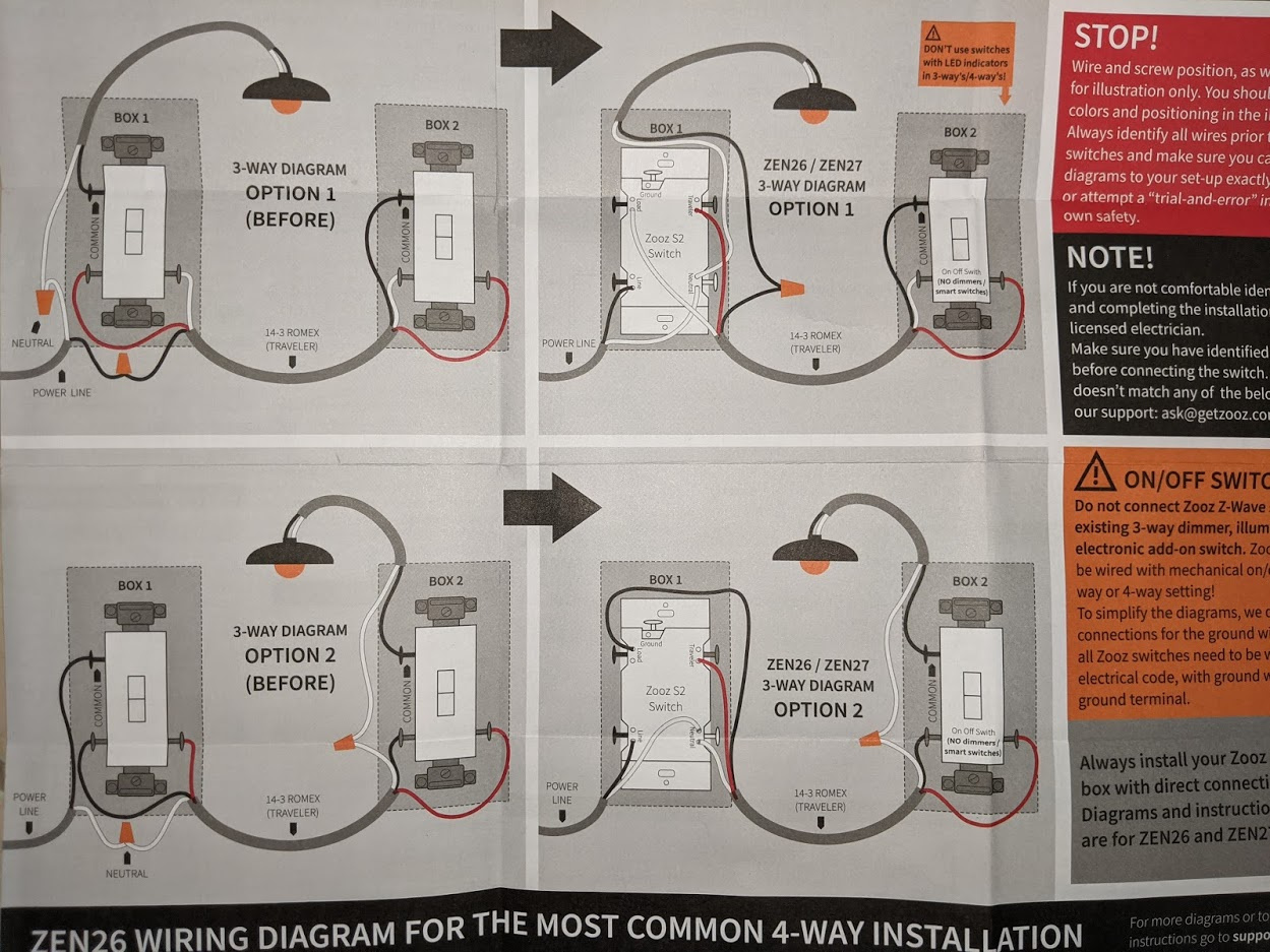
The first 2 I did were wired in the bottom configuration. It was easy to figure out what wire was what between connecting hot to it or just using an extra wire and a continuity test.
The one I'm trying to do now seems to be wired in the top configuration. How do I determine which neutral in the bundle goes to the fixture?
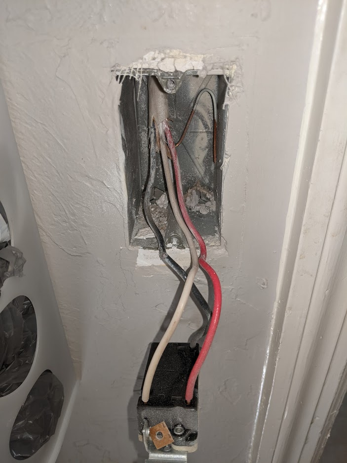
Here is the switch that has the hot wire where the Zen26 will go. I've marked the black wire with red electrical tape to remind me it's the hot wire.
Here is the other switch (the one on the left).
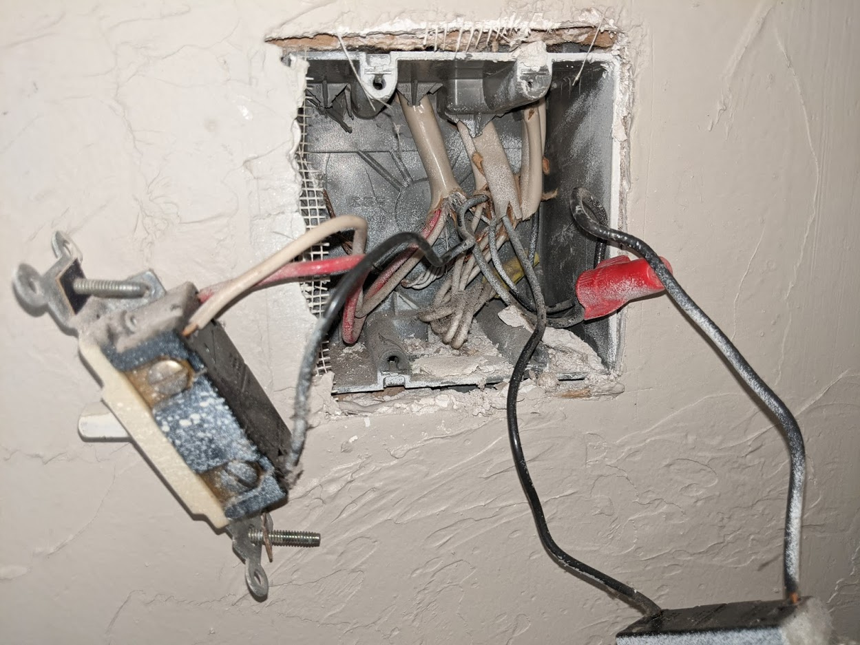
I used the continuity tester on my meter to determine that the red and white wires on each switch are connected directly. The black wire on the 2nd switch is presumably the load. I would have thought that the load and the bundle of neutrals would have continuity though, but they don't.
It's also worth noting that the black wire on the 2nd switch comes out of a different romex. I would assume the white wire in that same bundle also goes to the fixture, but I want to make sure and not just assume. The black wire that comes out of the same romex as the white/red wire is connected to the bundle of blacks, which is hot when the breaker is on.
Typing this out, it's occurred to me that my wiring doesn't quite match the top diagram in the instructions either. In it, the load is connected to the first switch that has the line wire. In my setup, it's connected to the 2nd switch. I may need to email zooZ support about it.
I drew out my wiring the best I could.
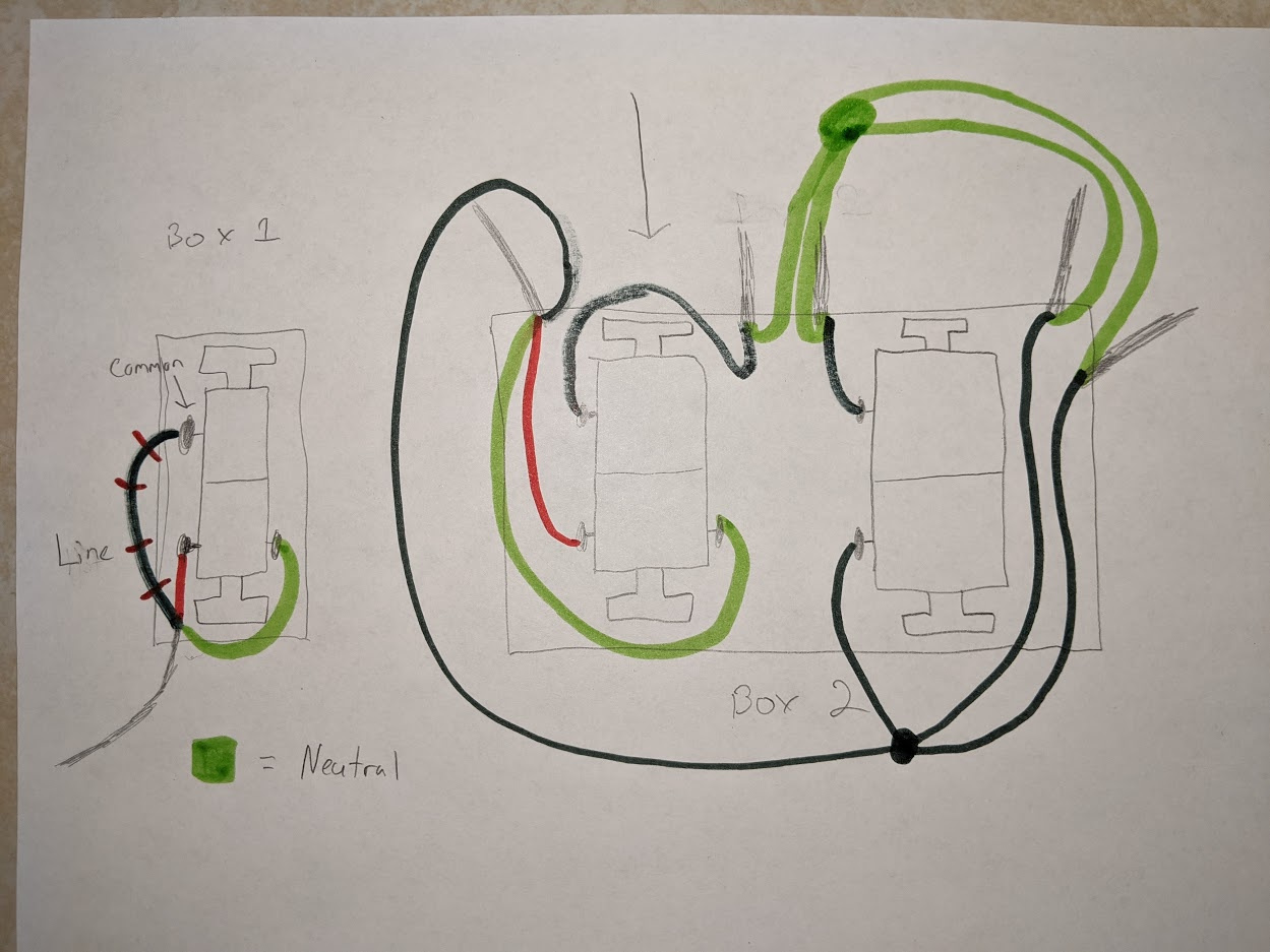
One thing to note, is that I don't think the line wire is actually the wire in box 1. It just is for the purpose or adding the Zen26 to this circuit. I'm pretty sure the actual line wire will be one of the two black wires coming from the right of box 2. I just have not disconnected them to figure out exactly which one because I don't think I need to.
I am assuming that for box 2, romex #2 is the load for the laundry room light I am wanting to replace the switch for. Romex #3 should be the load for the garage lights (that's what the other switch controls).
EDIT: I suppose I should have shown that the top left wire in box 2 is what connects to box 1.
The ground (bare copper) seems unconnected in your photos.
I've never lived in a house where the grounds are connected to the switches.
I guess it depends on code. I’ve never lived in one where they weren’t.
1 Like
I'm not an electrician, but I installed a GE/Jasco switch yesterday that was wired like that, only the white wire between switches was actually line voltage. Option 1 looks like white between switches is switched power. Not neutral. The white wire between switches in my case was directly attached to the black line wires in the box.
I think it was wired that was because the switch that was the primary switch, with the line voltage coming into it, had the light wires coming into it, so the primary switch had to be converted into a load switch, so hence the voltage on the white wire.
I figured that all the GE/Jasco switch add-on switch needs was a traveler and neutral, so I restored the white wire to neutral and tied off the black wire. It works great.
I realize that Zen26 is not the same. Another plug for the GE/Jasco switch is that you don't need to know what's line and load-it figures it out. Plus they're pretty shallow. Plus they have a nice blue light, lol.
I looked again, and just want to say I'm not a pro, so please don't kill yourself.
Looking at your picture it looks like a possibility could be the black wire between boxes is hot, with the source being in the lower picture box. It goes over to the upper picture box, and then comes back in white and red. The black wire on the lower switch goes to the load. The load gets its neutral from the romax that black wire is in.
That's just a theory, but based on what I saw yesterday.
For your wife’s sake, turn off all power at breaker.
1 Like
When you are testing for continuity, are the wires disconnected from the switches? Keep in mind that in the most common scenario, the two 3-way switches are single pole double throw switches. As such, the usual (though not guaranteed) meaning of white and black wires goes out the window.
1 Like
You don’t have enough wires to make it work here you need 4 for line, load, neutral, and traveler. Zen26 will have to go in the other box
The key to 3ways is the black/bronze screw which is your common. One will have line and other will have load. Just because your multimeter measures line in one box like this one doesn’t mean that is where line from breaker is. Often it is “sent” to another box, case in point is your setup.
But here is my trick, follow the wires from switch, especially the common wire, and see where they go. Notice in your 2 gang box the black common wire goes to a 14-2 wire where the white is bundled with other whites. In that situation that leads me to being load because if it was line, especially in a multi gang box, black wires are usually bundled with others in a wire nut.
Now you may ask why are you getting 120 at the single gang switch? Back in your 2 gang, ignore the black common wire, but follow the white and red to where they enter. Now where is the black wire from that same Romex going? It goes to a bundle of wires and one of those bundled wires goes to the other switch. Bingo, line from breaker.
So Zen needs to go in the 2 gang box.
1 Like
Yep... you're right. I would have figured that out eventually.
Right, I had figured that out and had shown in my drawing of my wiring, which I actually updated a little to include some labels to make it easier to talk about, and also made it more clear which wires connected to the one gang box.
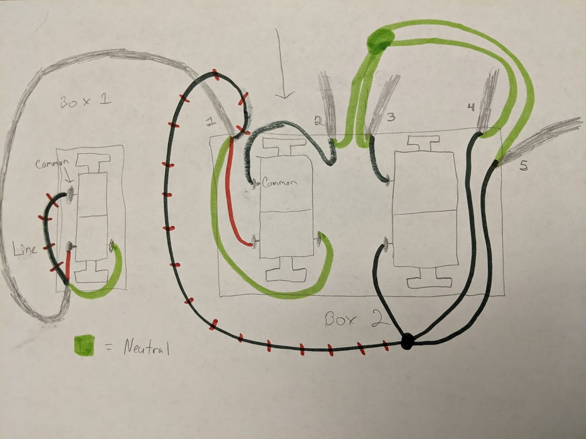
So line comes in from either 4 or 5 and then continues to the next device in the circuit from the other one. The simple on/off switch is connected to line, and the load goes out of 3. Then the black wire in 1 is connected to line. Which I think is why HAL9000 asked
Yes, they were disconnected from the switch.
I am not an electrician so I am trying to be super careful and triple checking everything, so it's been slow going. If I were to leave the switch in box 1 connected and then test the white wire coming out of 1... will it be hot? I think that's what you're saying. I can easily test that (though I don't know when... might have to wait until next weekend).
As a side note... I was really hoping I'd be able to put the Zen26 in the single gang switch. In the double gang box, I was planning on putting a Zen 30 double switch in place of the right switch (with the relay disabled. Going to eventually use it as a garage door button). I think it might be tough squeezing both switches in there.
I like that you are being analytical and thinking this through thoroughly. Perhaps it would help to understand how 3-way switches work from a more logical standpoint. While at first it seems like magic that nearly century old switches can control one light from two places without any smarts, it really is just a logic problem solved by someone brilliant back in the day:

So the reason I was asking if the wires were connected is because where you'd see voltage could depend on the position of the switches. You'd need to take that into account. Knowing the logic may help.
Note that this is not a representation of the wiring or content of your boxes. As you've seen in previous posts, there are multiple ways line, load, neutral, and traveler, and the fixture can be connected .. but in the end, all dumb 3-way switches work the same way.
Okay, that is what I had initially thought. I think I just read to much into what you were saying about the color of the wires. For the switch in the 2 gang box, the line wire will either be the white or the red wire coming from the first switch, depending on the state of the first switch.
@agnes.zooz would you happen to know the best way for me to wire the Zen26 here or should I email support?

