Homemade Environment Sensor + Arduino Shield

Hi Everyone,

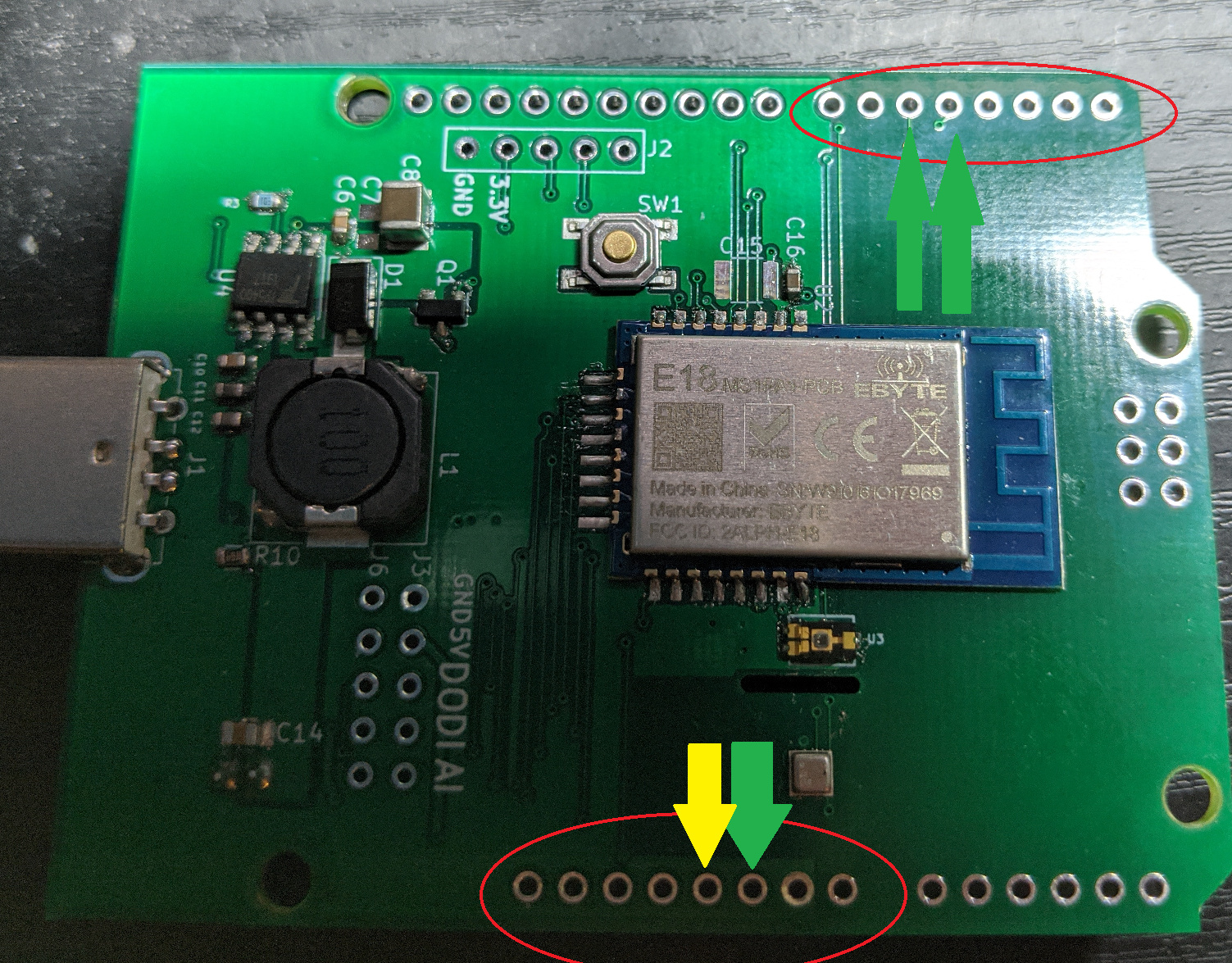
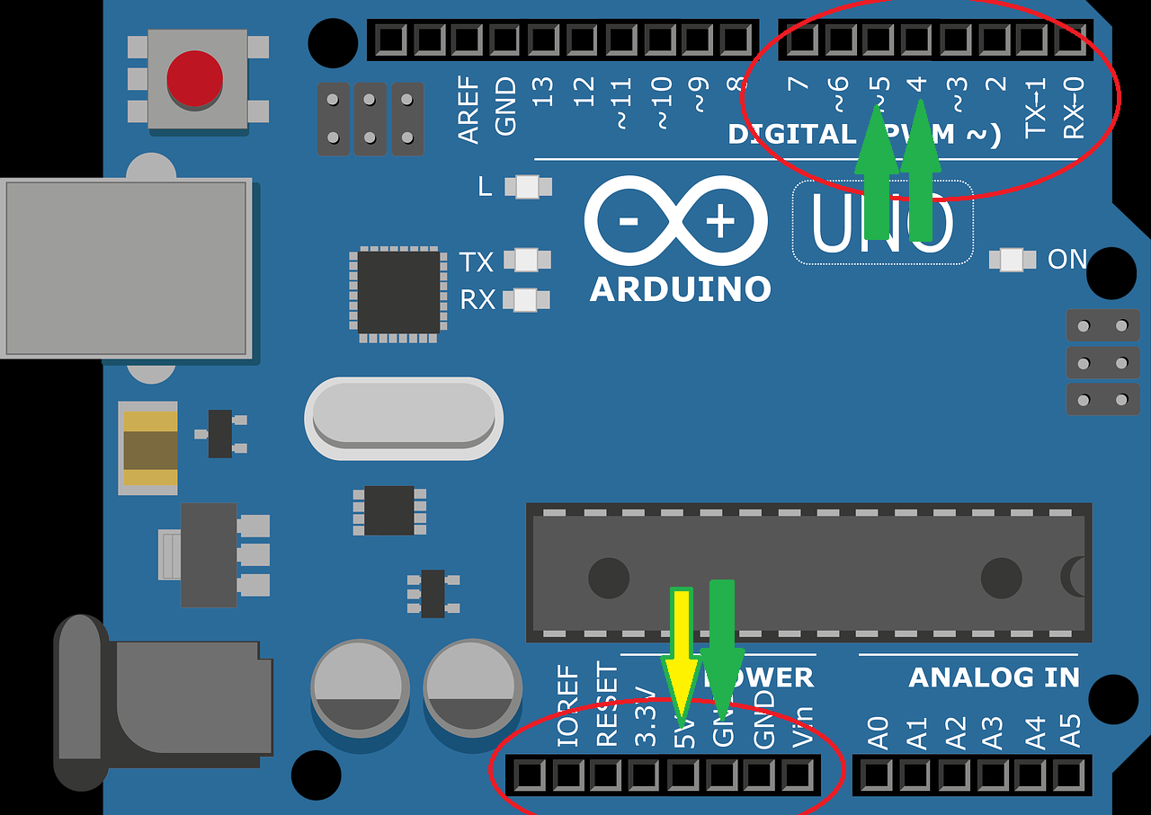
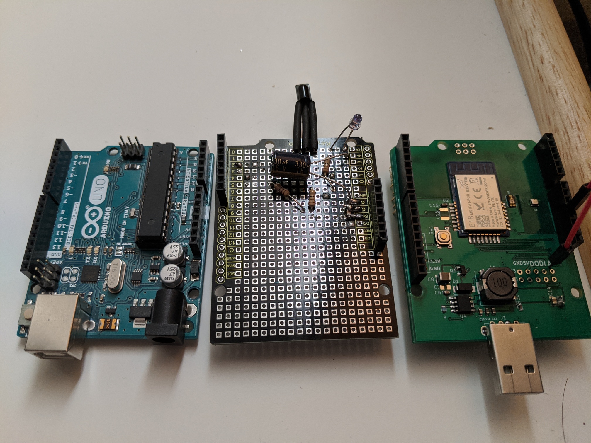
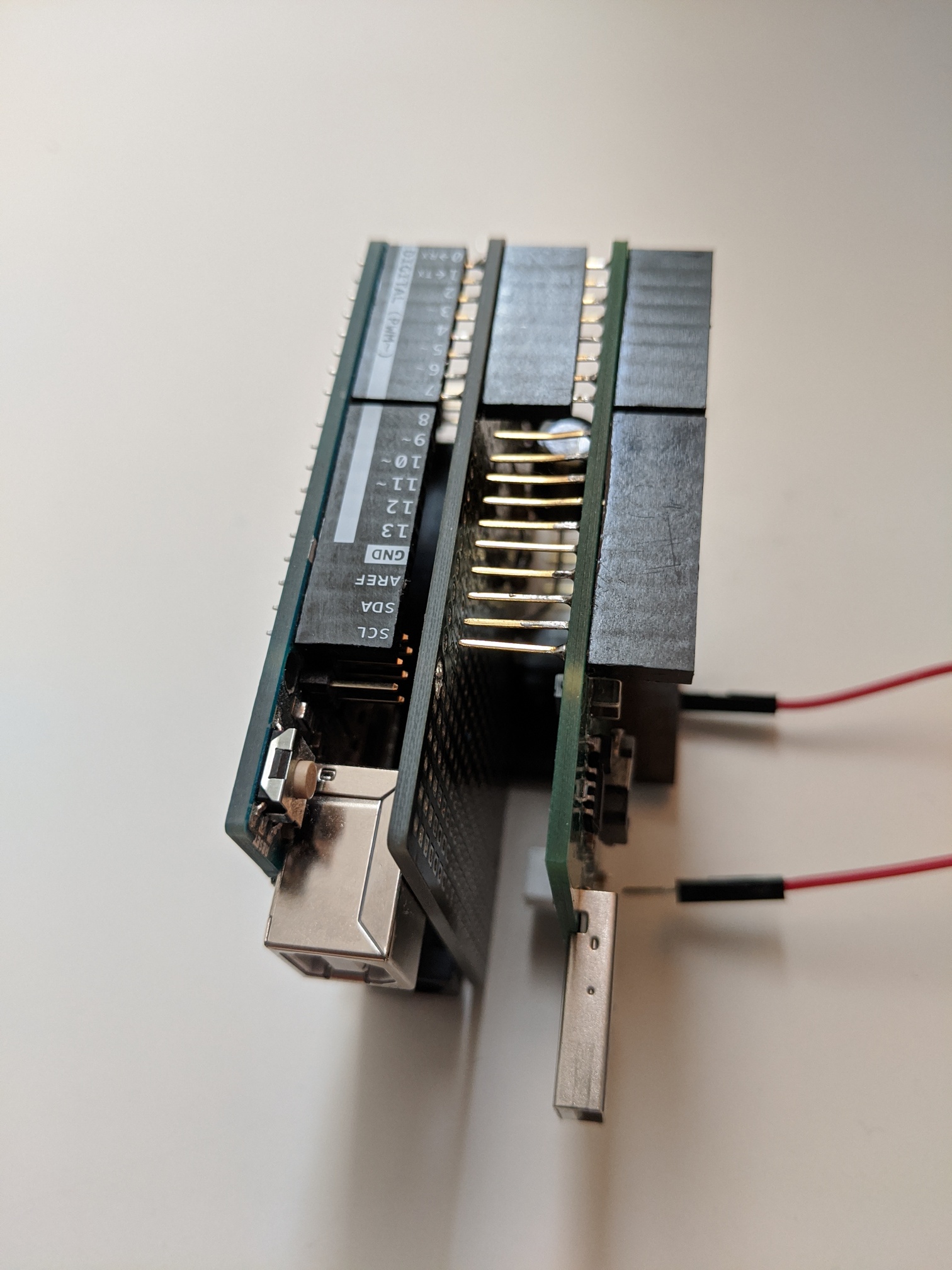
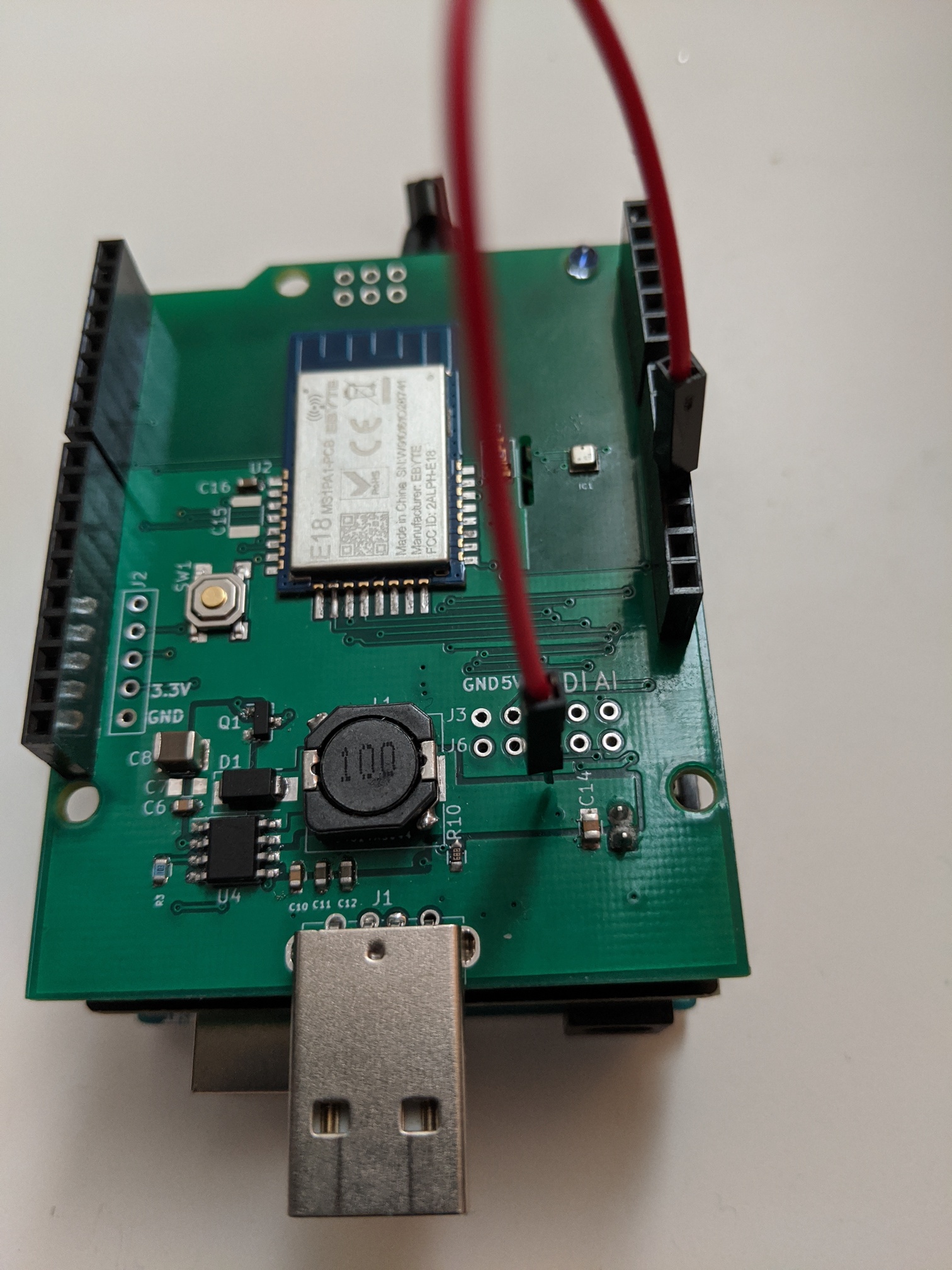
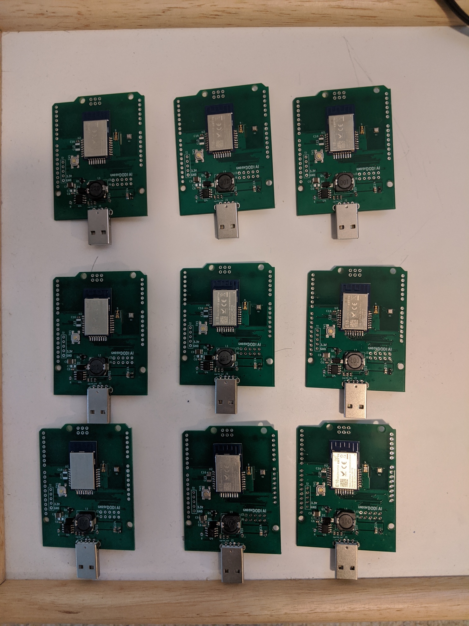
I like to introduce a new variant for my homemade environment sensor. This time, I make a Arduino UNO shield. This expand the environment sensor so that it can be used as ThingShield. I am aware of a few existence of ThingShield replacement.

My design is bit different. I added a Level shifter to properly handle difference in voltage between Arduino and the Environment sensor.

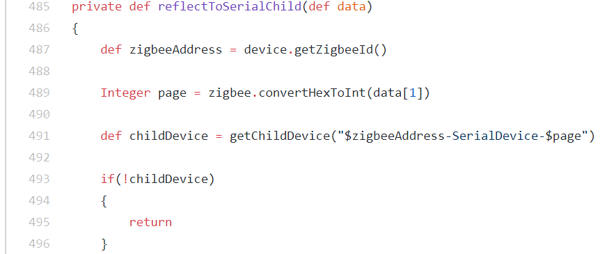
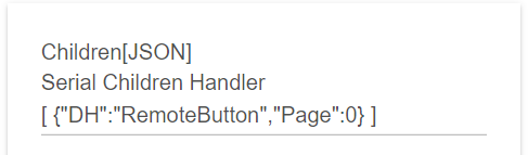
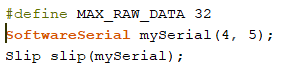
In software, I add SLIP protocol between the Environment Sensor and Arduino UNO. This will allow data sent in concept of a packet. It also open the possibility to send larger amount of data by fragmenting a larger packet if needed.

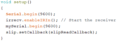
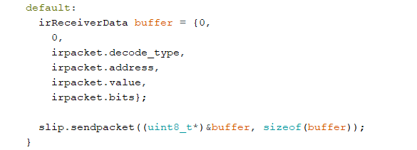
As an introduction, I make an IR receiver and IR transmitter to make some sort of universal remote control/receiver in the same box. If you have some time, please take a look at the demo.

If you are interested on the shield, PM me.

This module is based on the same module that I have been making here. It function as your Zigbee repeater that play nice with Xiaomi devices. It is battery backup and many others.

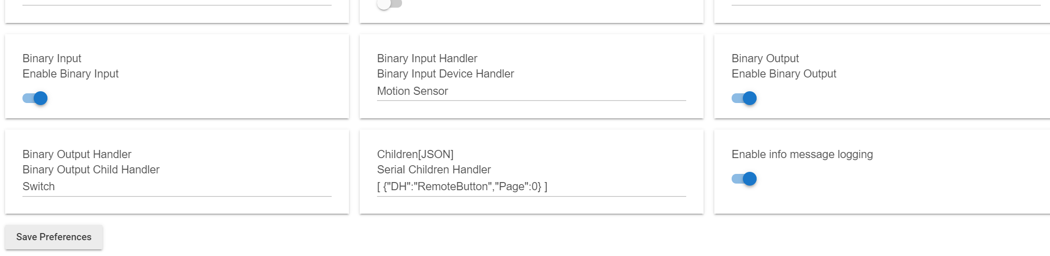
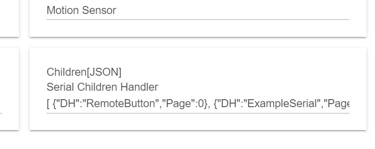
Example of Slip Library implementation here.
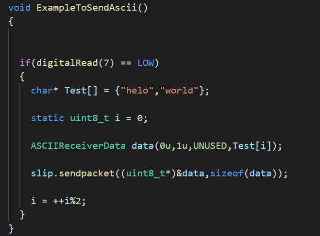
Example on how to use it from the IR demo video here.

Update1: Possible tachometer to measure fan speed.

Update2: Arduino Mega 2560 is available. Specific information about it is here on thread#47 I am making GPIO expansions. Here is a demo.

Update3: Arduino Due is available. Arduino due is a 3.3V system. The shield is designed to interface specifically to due. I am building massive relay system with it here.

6 Likes

DTH for IR remote is here. It is not anywhere complete. The purpose for this DTH is to illustrate how to send data back and forth with the serial device which is an ArduinoUno in this case.

You can think the Environment Sensor is just a Zigbee to serial port tunnel. This DTH can tunnel a binary packet to the Arduino. Arduino can also send a binary packet back to the DTH.

This binary packet can be in any form. The size of the packet must be less then 64 bytes. Just a note, since we are using SLIP. If you have escape character in your packet, it will use 2 bytes to send. This effectively reduce the number of byte you can send. In worst case, where all your data is an escape characters, you can only send 32 bytes in a packet.

The following is unique to my implementation. You can change it anyway you like. I always prefix my packet with [command][page]. Then, I follow with my data. Command and packet are one byte each. This allow me to multiplex the data to different serial child DTH. In the case when I have multiple sensor handled by the Arduino and would like to handle them with different DTH, I can assigned different page id for different sensors. if you look at my implementation of EnvironmentSensorEx.groovy, I have done something like below.

It is basically look at the page to find the child DTH to send the data. It is a way to multiplex the packet destine to its DTH.

The packet going to the Arduino also prefixed with page for the same purpose.

Since this example has only IR device, the page is set to 0. It looks not useful and therefore may confuse someone who read the code. I want to show my reasoning here.

And finally, there is a command byte. This has similar purpose. My reasoning is that have command that specific to the sensor. This command is 0. If I need a command in the future that not specific to the sensor but for the whole Arduino, I can assign a different command id. I do not have any specific one at this moment. I just set it to 0.

Having said the above, I want to make sure that you do not have to do it this way. If you decided to just modify the EnvironmentSensorEx DTH and handle your sensor attribute here, please feel free to do so. It is an example after all. The above is my idea of a packet would look like. For my own purpose, I am still developing these. I would eventually standardized my packet format. You are free to make your own packet format.

Update:
I forget to mention that If you are interested on using the example IRButton child DTH, you need to download the IRButton.grovy to your driver code. Then, you can add the DTH by adding the following in the EnvironmentSensor device page.

image

It will create child device. You can rename it later after it is created.

I am adding pictures and some information.

First connections pins from the shield to Arduino Uno.


At minimum, the connections to the pins indicated on the green arrow must be made. They are ground, pin 4, pin 5. The pin 4 is used for serial RX on the Arduino side. The pin 5 is used for serial TX on arduino side. You can make these connection for initial testing using jumper cable. You will need to power the arduino and this shield independently. If you need to draw power from the shield to your arduino board, you need to make connection indicated by yellow arrow. If you make the yellow arrow, you should not power your arduino independently.

Of course, using jumper cable is not the way to go for long term. You can skip the above and just solder headers like below.

I just want to make sure you got some idea about the dimension of the shield.

One important note about the red jumper.
Arduino has its own power supply. When you are developing your code, you are likely be powering the Arduino from them USB. My shield have its own power supply (battery or USB). If you accidentally have the jumper connected in short term, It would be fine. Do not panic. I have done this in the past. But, it is not save. Yes, both roughly generate 5V at that point of connection. In theory, it is just like 2 battery in parallel. But, they are not battery after all. remove the jumper and be safe rather than sorry.

Once you are done developing (unplug your USB), your Arduino should need a 5V power. At this point you can draw 5V power from my sensor by using jumper cable to Arduino 5V pin. Your Arduino will get power from my sensor and all the benefit of battery backup.

The red jumper wire can be eliminated. But, you will have to short a jumper at the back. Please note, again, in this case, you will be drawing power from the shield. You should not power your Arduino independently if you do this. This is doing just like the red jumper above except without cable. This will give it a cleaner look. There is no cable running around.

You need to install ICSP header at the bottom of the shield. This header is typically included if you purchase arduino header kit. This is what it looks like.

The serial port of the Zigbee MCU will be connected to pin 4 and 5 of the ArduinoUNO. Pin 4 for RX and 5 for TX from the Arduino perspective. I use SerialSoftware. You can use any serial bit bagging library available. I want to keep the HardwareSerial for the Arduino standard use. It seems that in Arduino world "Serial" object is heavily used as debugging. I do not want to loose that functionality. I choose to use other pins.

In arduino, here is what I basically do.

image

and in the setup.

image

After all these, I use the slip to send and receive packet. We are not going to deal with serial port anymore.

image

1 Like

Absolutely love your hacks. Keep it up!

2 Likes

Thank you.

1 Like

Update: The board assembly has been completed.

A few of them has been spoken for. I only have less than a handful to share at this moment.

Thanks
Iman

1 Like

@iharyadi - Iman, can you please explain the purpose of all of the pins in the J2, J3, and J6 connections? I am trying to fully understand this very interesting UNO Shield you've built. I need to know which contacts should have pin-headers soldered to them to make it easier to connect wires.

I did run into one problem - it appears that the battery connector on the bottom of the board mechanically interferes with the UNO's black barrel-style power connector. I tried to find the extra long Arduino UNO Headers to purchase (like the ones used on the Arduino Ethernet Shields), but those are difficult to find. The exposed pins on those are ~15mm long, versus the more common headers are ~10mm. Those extra 5mm would keep your shield safely away from the UNO board's USB and Power connectors. For now, I just moved the battery connector to the top of the board, being careful to maintain proper polarity.

Next step is to figure out the serial communications between the Arduino, the Shield, and the Hubitat Driver.

UPDATE: I am also having some difficulty getting the BINARY INPUT and ANALOG INPUT attributes to update automatically. They are enabled in the user preferences, however the attributes in Hubitat only update when I manually click REFRESH. Not sure what the issue is? :thinking:

1 Like

I am glad for your question. Please do not use pin J2. It is a programming header for the Zigbee module. At this point, please do not use J6 as well. It was a set of extra pins connected to available GPIO pin. We do not have GPIO pin at this moment.

The J3 is the regular expansion pins. This is the same set of pins as the old modules that I have. One of the pin marked 5V is what you want, You can use this to power your Arduino after development. During development, your Arduino can draw power from the USB. My shield and the Arduino ground is connected if you are able to connect them through the headers.

After development, you can draw power from the said 5V and connect it to 5V pin on the Arduino.

This is a great solution. I opt not to do that for myself just I do not want to have the battery on the front just for aesthetic reason. During the design, I think that there should be at least one middle mezzanine where other sensor can be placed. This will clear the battery issue as is.

Just to visualize the connection, here what you need to connect.

The green arrows are minimum connection you need to make to the same pin on the shield. The Yellow arrow is a connection that you may want to connect to the J3 5V if your arduino is not powered from the USB. You can make these connection for testing. This is what I did during my early testing. I just use jumper cable to make the connections.

For convenience, you can solder headers shown on the red circle to achieve the same purpose as above once you feel that you want to go a bit more permanent.

In the long term, all headers should be soldered so that the boards stick much better.

Thanks
Iman

1 Like

There should be children DTH installed for them. The children will setup the reporting so that they will update. Here is what I do to test them.

For the digital output, please use switch dth as example.

For analog input, please use the MQ9 DTH for example.

You can then connect jumper wire between DO and AI. Then, you can use the switch to turn on and off and see those value updated automatically.

You can do the same between DO and DI. The DTH are examples only to test those pins. For DI, you can look at/use the "Motion Sensor" child DTH in the same repository to try it,

Here is my example test setup.

1 Like

Thank you very much, Iman! This is exactly the information that I needed. I am making progress now.

1 Like

@iharyadi - I believe I found a small issue in your latest Environment Sensor Ex driver. There is a reference to SERIAL_TUNNEL_CLUSTER_ID(), which I believe should return 0x1001, however that function is not declared anywhere in the driver. I see where other 'serial' device calls all reference 0x1001, so I assume that is the correct cluster ID for the new serial Shield communications, correct?

1 Like

Yes. That is correct.

One more question... Is SLIP required? In other words, is your firmware on the shield expecting SLIP data packets? Or is there a simpler way of simply transferring ASCII string data?

1 Like

Hi Dan,

Yes. SLIP is required to communicate to the firmware.

I believe you can send the string in the SLIP buffer. It is just on the DTH side that you will get HEX string rather than the string. The HEX string can be converted to the ASCII string I believe.

Thanks
Iman

1 Like

Hi Dan,

I remember that I did something like below to convert it.

byte[] bytes = Hex.decodeHex("THIS_IS_THE_STRING_FROM_THE_ZIGBEE_IN_HEX");
String fromArduino = new String(bytes, "UTF-8");

Thanks
Iman

1 Like

Hi Iman,

I am struggling to get the serial communications between a simple Arduino sketch and the Parent Driver to work.

I am able to use the IRButton child device to send the "TransmitIRTest" and "TransmitUnknowIRTest" from the hub to the Arduino and this data is received. So, I know the data is flowing and my wiring is correct.

However, I have not been able to get data from the Arduino to the Hub, as I do not have the components to build an IR receiver.

Would it be possible for you to create a much simpler, stripped down set of example code? What I am thinking is a simple Hubitat child device driver with a custom command that allows one to input any string they would like (limited to 32 characters) and have that string data appear on the Arduino. Likewise, a simple sketch that can send any string to the Hub and have it parsed correctly to be used to update an attribute.

Let's take all of the Infrared stuff out, to make a much more generic, simple example. This will help many users, in my humble opinion.

Thoughts?

Thanks,
Dan

1 Like

I will do that. Let me work on it and update you once I am done.

I am a little busy today. I would say I may have something done by the weekend.

Thanks
Iman

1 Like

Thank you Iman. No rush.

Hi Dan,

I have just a bit of time and throw out an example. Let me know if this is not enough.

In arduino, I added the following.

image

I added a new example DTH.

You can add it to your device code and add it as child device of environment variable like below.

The JSON is [ {"DH":"RemoteButton","Page":0}, {"DH":"ExampleSerial","Page":1} ]

You will get a child device like.

Any time you short pin 7 on your arduino, you will see word "helo" and "word" cycle through in the ascii attribute.

The code that make it happen is in the parse method of ExampleSerial.groovy.

Thanks
Iman

Ps. please update the slip library. I am making changes for the up coming Arduino Mega 2560 shield.

1 Like

I’ll give this a try hopefully tomorrow. Our ISP service is down tonight due to some storms passing through the area.

Thank you very much!

1 Like