Hey, I have a question. When you used the zen53 controller to the flair mechanism, can you draw a schematic of the circuit? I purchased 2 vents and 2 zen53 controllers. I took one apart to prepare for this modification. I did test my zen53 will only work with 6+ vdc. Thanks
I don't have a drawing but schematic is very simple. The 15ohm 5W resistor connected to the motor in series. That is it.
My ZEN53 works very well starting from 5V as stated in the ZEN53 spec. I did not found a spec for the DC motor used in Flair vents. So, I tested the motor with variable ps and motor works just fine with only 2V DC. So, the serial 15ohm 5W resistor serially connected with a motor compensates for voltage difference. I already had/have 12V DC power source nearby. So, I added 12V-to-5V down converter. Electrycally this is it.
Mechanicaly I had to destroy a battery compartment in order to fit ZEN53 and DC downconverter.
My ZEN53 are older firmware revision. If you open/close them few times the physical position is shifted and after a few cycles it needs re-calibration. This was fixed in the latest firmware but I did not bother to update. Instead my RM rules hommed (100% open) vents as a first step and then the desired position is set. ZEN53 is capable to control a position in a range 0-100% and i am using this in my rules.
Ok,so you have 12vdc handy. I do not but I will make it work somehow.
So, you have 12vdc on the power lines for zen53. Then on the output for the motor, you installed a voltage regulator to only allow 2vdc to the motor? This is the part where you lost me.
When I put the motor leads on my meter, it shows no voltage until the zen53 is activated, then it will either send + or - 12v to motor leads. Do I have that logic correct?
Then you take your 12vdc and drop it to 5vdc to power the zen53? I tried to connect it to 5vdc on the supply line but it would not power on until I hit 6vdc on the meter.
Now, what about the limit switches? There are 2, one for fully open and one for fully closed. From your initial setup, you wired them to the input on the zen53, correct?
Thanks for the assistance.
Paul
You can use whatever DC PS you have around with output voltage in a working ZEN53 range. 1A should be enough. The ZEN53 dc input range is 6-32V (I was mistaken about 5V since the project was done long time ago). This DC downconverter powers ZEN53 itself (not a Motor!). Since motor is working fine with only 2V DC (it may take higer voltage but since I did not find a spec for the motor I have no idea how high voltage could be without damaging a motor) you need a resistor serially connected with a motor. If you use a higher input voltage you will need bigger resistor (both Ohms and Watts). This resistor is nothing more than very inefficient voltage downconverter (it simply keeps voltage acros motor down to 2-3V).
Yes, ZEN53 will output a voltage close to the power supply voltage only when it is active. This is the way how it works. And a polarity is depend on the open/close commands.
Now, what about the limit switches? There are 2, one for fully open and one for fully closed. From your initial setup, you wired them to the input on the zen53, correct?
S1, S2 inputs are for manual open/close control (at least in my case with original firmware). So, this inputs are noy used at all. If latest firmware allowed to use S1, S2 inputs a a Limit Switches then yes, you can connect Flair Limit Switches to these inputs. Otherwise leave them unconnected.
Just in case here is a quick schematic sketch:

Ok, so thanks for that. Lol. It seems like this zen53 does a lot of the work. I guess that's good, right? Shoot, maybe I can even use some of these zen53 controllers to change my solar panels angle (with existing linear actuators. It only adjusts on the first of each month so it should work like you have it setup to adjust back to the zero point before setting the angle by time moving. Whatcha think?
I guess it is time to solder in the new controller and see what happens. Lol
In theory, YES. Please keep in mind, current rating is only 1.5A which most likely is not enough for driving linear actuators. My good guess, they may need 5A+ capable drivers. You can build DIY Actuator Controller based on Habduino + High Curent H-Bridge.
Sure. My setup is woking just fine for almost 2 years.
The actuators don't pull much. I will solder one up to an amp meter and test it. It does not sound or look like it is struggling, but you never know.
I was hoping it would work, and maybe it still will.
What I am doing is my solar panels are adjustable for the angle to the sun. I know the degrees it needs to be, but as it is right now, I have to take a battery outside and then I watch the angle while applying the power to the actuator. I will let you know how it goes.
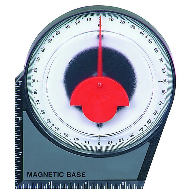
I just wish I had a way to actually measure the angle and adjust from there but I can work with timing it like you have for the vents.
The actuators don't pull much. I will solder one up to an amp meter and test it. It does not sound or look like it is struggling, but you never know.
I was hoping it would work, and maybe it still will.
What I am doing is my solar panels are adjustable for the angle to the sun. I know the degrees it needs to be, but as it is right now, I have to take a battery outside and adjust them with the battery and a analog angle meter.
Any ideas?
I forgot to ask, does the zen53 report the voltage being used?

For current measurements you will need to know a Peak Current. Multimeter is too slow for this type of measurements. You will need a Current Sensor and Oscilloscope. Or simply check the actuator spec. It should tell you what is a max current and average drive current. Then use an appropriate H-Bridge with current rating above 20% max (not avarage) actuator current.
What is an output from your analog angle meter? Is it a Voltage proportional to the Angle. In this case you can use ADC. There are few devices with ADCs. But if this is me, I would create a Hubduino/ESP32 DIY project.
Nope. I am looking for an answer to to this problem.
I would like to know the angle of the panels so they can be adjusted a couple times a month to keep getting full solar during the day. Granted, if I knew the angle, I could adjust it daily. I hope that made sense.
Another job I have is to monitor the voltage of my solar battery bank to make sure I address any problems quickly so I do not destroy my battery bank. High voltage would be anything above 28.8vdc and the lowest would be around 21vdc.
Thanks for thinking about it for me. I imagine many could use this setup.
Hubduino/ESP32 DIY project.?
Please explain....what is involved. I have some old Arduino processors that could be repurpose for this project. I was learning how to use them before my accident in 2013. I have a TBI and it affects mostly my short term memory.
I am sure with some help I can accomplish these setups and more. I do not even know how to make a Arduino talk to the HE hub. I know, another lost cause.
There is a software Hubduino project (please search a forum for the detailes on Hubduino) designed spesifically for creating WiFi DIY Devices for simple intergation with HE. Hardware platform is ESP32 plus whatever else you want to use. For the software project you will need an experience with Arduino IDE. For the hardware portion you will need a soldering skills and anderstanding how to interface your sensors and actuators to the CPU. Mainly this involves matching voltage levels. If you are not comfortable dealing with sw/hw then (unfortunately) this DIY projects is not for you. Please read about Hubduino and decide if you will be comfortable with such a projects. Unfortunately I cannot provide you all the required details how deal with hw and sw but sure, definitely can give you some general ideas.
OK, this one does not have any electrical interface at all.
Here is an idea.
Since you need only 12 (fixed?) positions you can build very simple linear encoder for positioning actuator. This could be a metal rail attached to the actuator with 12 holes. Location of holes shoul represent a desired actuator position. Then simply optical hole sencing sensor will tell you when actuator moved to the next hole, i.e to the next desired position.
Alright. My resistors arrived today. I added it to the vent and you are correct, it allows ~2vdc to pass. After I connected it up, I hit calibrate and it opened and closed the shutters pretty quick. Now, if I press close, it slams closed. Press open, it slams open. Many times, I have to help it go the other way because it is getting stuck at each end of motion. Also, on open, it opens, then clicks a bunch of times and then it will stop. Any ideas would be helpful. Thanks.
First of all - I assume the resistor is present. In my case voltage is 6V and resistor is 15ohm@5W. If ZEN53 voltage is higher that 6V the resistor value also should/must be higher.
This project is near 2 years old. Once it was done I never touched anything and therefore all little details are forgotten. It works just fine.
The ZEN53 firmware version is 1.10 With this firmware calibration quicly derails after only few open/close cyckles. For this reason in the rm rules the vent position is controlled by two sequential lines. First command ia always "Close" followed by "Set Position".
I wish, ZEN53 could use a Limit Switches but atleast with 1.10 firmware this is not a case.
Because motor slams it looks like something is not right with calibration. I do not remember if memory servse me well I entered the related parameters manually.
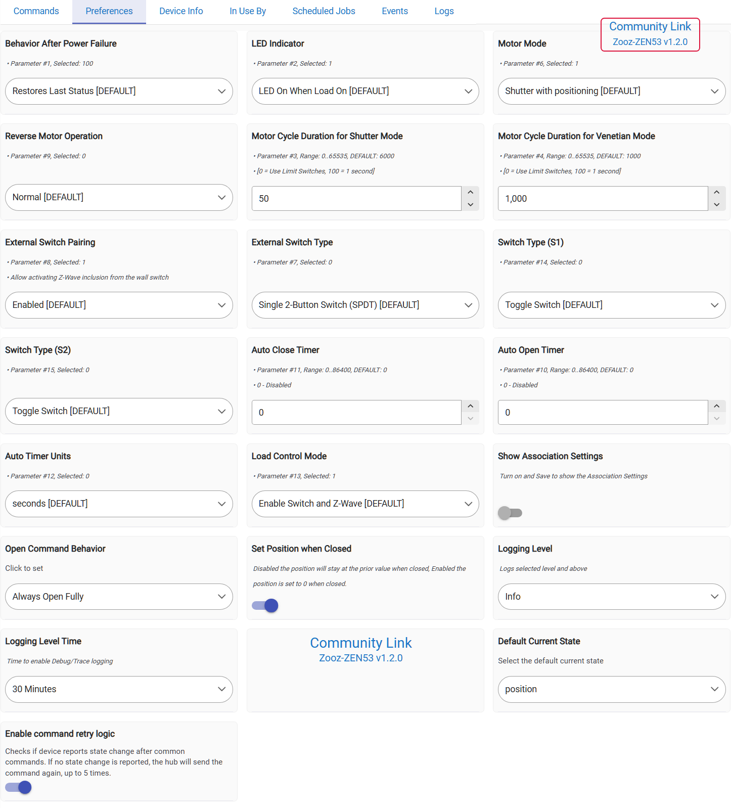
Just in case here is a device "Preferenses" page:
And finally which Driver are you using?
I am using Cistom Driver:

