DIY- Battery Backup Hubitat- under TEN bucks-NO soldering

Hmm. Anyone have any ideas why I'm seeing the problem I do? It sounds like people have been able to make these work without modifications. I'm not opposed to soldering, but what I really lack there is honestly skill/manual dexterity/making-it-look-like-a-five-year-old-didn't-do-it and not eyesight. :slight_smile:

Could it be my batteries? That's about the only variable I haven't significantly changed yet, despite trying several kinds I either ordered for this purpose (and the seller for which, Battery Junction, I've historically trusted) or already had on hand (though I have no idea what those were as they came from pretty cheap electronic devices). I have used a few different loads, some presumably quite light, but both they and the hub all show this problem.

It could be, poor quality or worn out batteries may struggle to supply the current required when mains power is removed. I got some Panasonic-Sanyo 3500mAh batteries and they can even run a Pi 3B+ without the dreaded yellow lightning bolt appearing.

Just ordered two from LiIon Wholesale. Hopefully that's the secret...otherwise I'm not sure why these seem to work for everyone but me. :slight_smile: Thanks for all the ideas, everyone. We'll see in a few days!

1 Like

We should be sure we know what board you actually have. Can you post the bottom of your board?

Are you sure you have the battery in the correct way? Not trying to suggest you are that ______ but on mine the battery holder was in backwards. If I put the battery in the way the holder indicated it would be in wrong. The + on the board is the correct marking.

If it gets to a point where measurements are helpful do you have a meter?

John

That's the case for my 4 too - I never even looked at the battery holder until now because the PCB + / - markings were visible.

I got a mate to print me out a few cases for my backup units - looks great in white with the LED's shining through the base. :+1:

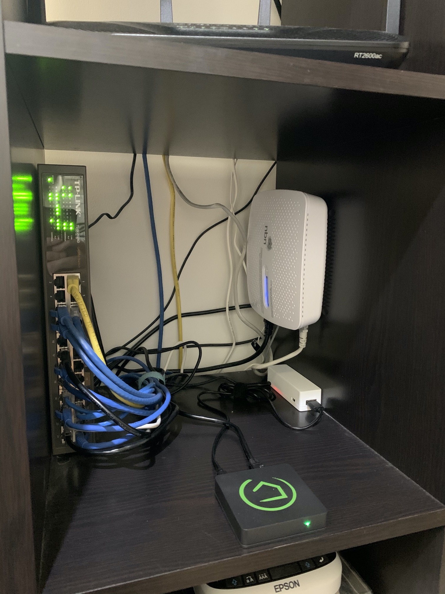
I recommend folks use the modified version as the OG model causes issues for some slicers.

4 Likes

In my quest to find one that worked, I actually ended up with four different boards now that the remaining one I ordered arrived. :slight_smile: Here are the front adn back of each:

Board 1: (did not work)

Board 2: (did not work)

Board 3: (did not work)

Board 4: (works!)

The biggest difference between the one that works and the ones that don't is that the one that works (board 4) has a "hard" power switch on the side:

The ones that don't have just a button, which in my experience just turns it on if off (though it's not necessary to press after losing AC power; it will come back on its own, but with the problematic delay):

Having seen the real switch in one of the products above (that someone claimed to work), this is what I looked for in my latest attempt at board-finding. So far, so good on that one! Not sure how to explain the difference, but this is what my experience is. (The batteries I have all work fine on this one, by the way, though as mentioned previously I do still have even more of those coming, too.)

2 Likes

And, no USB C connector.
I saw that mentioned in an Aliexpress review and wondered why it mattered, guess we know now.

1 Like

Your IMG_1802 (8 of 10) is the board I have. The difference is the IC's used for the different functions.
The difference is the 24 lead IC in the middle. Attached is the board I have with some annotations of different functions.

I was pretty impress with the board (for the $$). However I did not like the connectors. I took them off and soldered in short leads. Actually I purchased a Micro USB extension cable. Cut it in half and used to adapt the Hubitat connectors.

The board is working well. During the solder in process I has a short on the 5V. Didn't phase the board. It just shutdown and when I removed the short it came back to life.

Hope this helps.

2 Likes

That micro b connector is very weak. I broke one off one of my boards very easily.

I fixed it by super gluing it to the board and resoldering it.

I also broke the micro-USB connector off the board above, though it was my fault since I thought I had everything unplugged before I started pulling on the cable to move it to another board. But I'd still be careful. :slight_smile:

Thanks for the advice above! I think I'll resort to using the "other" boards for things where brief power interruption doesn't matter, like USB repeaters--or possibly nothing at all since I probably have way too many now after trying so many. (I don't have the electronics skills to work around whatever issues there seem to be with the others, but they're apparently not all the same--so unless anyone has better advice, I'd suggest anyone looking to try the same find one that looks like the ones known to work well for hubs, like the one above).

1 Like

@bertabcd1234 I'm pretty sure it's due to how long the battery takes to deliver the required current to the end device when power is removed. The battery never delivers any current UNLESS the load requirement exceeds the maximum output of the charger chip. Therefore when mains power is removed there will always be a small dip in output when the battery kicks in. This is normally for a pretty short time but obviously long enough here to affect your particular hub. Hopefully your new batteries will be better at this. Are you also able to test with a different model hub?

I'll see when my new batteries come in--maybe that will help! But any battery I've tried works for me on the "good" board and not the others, which is all I can say at the moment. I have tried on several different devices (USB voltage tester, Xbee, etc.) and hubs. I might have skipped one or so, but I have one of every Hubitat models C-3 through C-7 and haven't found any device that tolerates this dip yet. :slight_smile:

Sorry didn't read the entirety of that post - too many mesmerising photos! Those must be soft off buttons ( they aren't mechanical latching buttons right?) which probably introduces enough of an additional delay when switching off and on during battery transfer to cause issues.

Yeah, the "soft" vs. "real" button difference is the biggest difference I can see (besides the fact that other parts of the board are different, but that's of little use to my untrained self). Since I saw someone above who claimed that a board that looked like that worked for them, it was something I threw into my last order to see if I could get one like that to work, too.

yeh additional electronics in the output path. Good to know we should avoid these.

Fortunately this is not the case. There is no dip as the battery immediately supplies power when charging current is interrupted.
As I said I have one and have monitored the output with an oscilloscope and there is no significant dip. By significant I mean the output drops but does not drop below the USB spec for 5V. I did not verify but I'm pretty sure the dip is caused by the 3.7 to 5V step up converter responding to a change in input.

Of course all this only applies to the board I have. I can't comment on the other boards.

1 Like

If you get a chance, I would be curious to know what partnumber the 24 pin IC is.

I found the same thing.

I can definitely try to figure that out if there's a good way for someone who isn't an electrical engineer to tell. :smiley: (To further point out my lack of knowledge here, I assume it's the IC with 32-ish pins sticking out from it, the only thing I can see that I assume might have anywhere close to that many inputs?)