Thanks! I did find that "Product Description" text now (which I previously ignored as I figured it was more marketing  ). Adding an RC circuit is probably above my skill level, but I still appreciate that knowledge! I am still curious if people have found ones that work without interruption or if I might be doing something wrong.
These all should run the same charging circuits as the singles so should not have a discernible delay.
When connected to power, the board is supplying current to charge the battery and power the USB output. When power is out the battery will discharge to power the output. There would be some delay as it depends on how fast the cell can ramp up to the voltage needed to drive the output (5V step up) circuit.
Have you tried with a smaller load (say arduino) ? I assume you also started with (both) fully charged batteries before disconnecting.
I didn't try with an Arduino, but I did try with an Xbee, which I assume should also be pretty low power. I also tried with one of those "USB voltage testers," though I don't know how much power they consume on their own (but mine turns on more or less immediately when plugged in to the board on either AC or battery power; it turns off for 1.5-2 seconds or so if it is plugged in while the board is unplugged, going from AC to battery).
Maybe it could be my batteries? They were fully charged during these tests. I'm not sure if one advertised for "high drain" would fare better. I suppose I could try a particular set recommended from the store above if nothing else (even though I've always had good luck with Battery Junction and have a few different kinds of Samsungs and a couple more others).
Your link to Aliexpress Single cell no switchover is the same one I have. It does not have a switchover problem because it doesn't switchover.
The functions are:
- Charger charging the 3.7V cell (to 4.1v)
- The 18650 cell
- Connected to the cell is a 3.7V to 5V boost circuit.
The 3.7 to 5V boost is running off the battery 100% of the time. At the same time the Charger is charging the battery. It works perfect for the Hubitat hub. However if you try to apply it to a device drawing more current than the Hubitat the charger will not be able to keep the cell at full charge.
BTW This board also has a battery protection circuit that disconnects the battery if it is being over charged or over discharged.
According to Andreas Spiess, the battery charger chip is supplying both charge current and load current. The battery only begins to discharge if the load current exceeds the current deliverable by the charger chip (generally when power goes out).
That is correct, however the charge current is limited to approx 600ma. The Hubitat hub draws ~300 ma when "idle" (C4 measurements) and jumps to above the 600ma charge current for short periods of time (during activity).
This means periodically the battery is asked to add some current to the charge current to carry over the current peaks.
The charge current can easily be increased (or decreased) and I thought of changing it but after weeks and weeks of powering my C4 the battery stayed at full charge. Besides most folks (not all but most) would balk at changing an 0805 resistor.
Agreed - just wanted to clarify your original statement.
True, although I have done 803's on occasion. Although not helped by ageing eyesight!
EDIT NOTE: It's a pity that the description for the board is actually somewhat misleading as it can't actually deliver anywhere close to the 1.7A demonstrated by Andreas let alone the advertised 4A indefinitely while powered due to the limitation on the TP 4056.
I find I need 5x magnification for all soldering these days, my eyes just aren’t what they used to be. ![]()
I find 0805’s harder than QFP’s - can you tell? ![]()
Yep same here! ![]()
1 Like
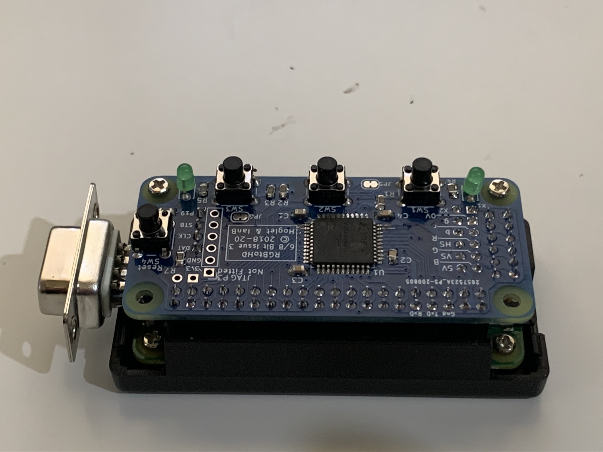
BTW What is that hat?
RGBi TTL to HDMI conversion hat for the Pi W.
I thought it might be fun to build 20 of them. 
1 Like
With the Andreas Spiess video (he always does a great job) it is easier to understand.
BTY if you look at the data sheets for the 3 main IC's, the board design is simply a combination of the 3 "reference" circuits.
The worst I've had to solder was, I recently inadvertently chose a SOD932 for a transient diode. It looked plenty large on the screen! Would not want to do any of those again.
LOL, those things are tiny!
1 Like
Hmm. Anyone have any ideas why I'm seeing the problem I do? It sounds like people have been able to make these work without modifications. I'm not opposed to soldering, but what I really lack there is honestly skill/manual dexterity/making-it-look-like-a-five-year-old-didn't-do-it and not eyesight. ![]()
Could it be my batteries? That's about the only variable I haven't significantly changed yet, despite trying several kinds I either ordered for this purpose (and the seller for which, Battery Junction, I've historically trusted) or already had on hand (though I have no idea what those were as they came from pretty cheap electronic devices). I have used a few different loads, some presumably quite light, but both they and the hub all show this problem.
It could be, poor quality or worn out batteries may struggle to supply the current required when mains power is removed. I got some Panasonic-Sanyo 3500mAh batteries and they can even run a Pi 3B+ without the dreaded yellow lightning bolt appearing.
Just ordered two from LiIon Wholesale. Hopefully that's the secret...otherwise I'm not sure why these seem to work for everyone but me. ![]() Thanks for all the ideas, everyone. We'll see in a few days!
Thanks for all the ideas, everyone. We'll see in a few days!
1 Like
We should be sure we know what board you actually have. Can you post the bottom of your board?
Are you sure you have the battery in the correct way? Not trying to suggest you are that ______ but on mine the battery holder was in backwards. If I put the battery in the way the holder indicated it would be in wrong. The + on the board is the correct marking.
If it gets to a point where measurements are helpful do you have a meter?
John
That's the case for my 4 too - I never even looked at the battery holder until now because the PCB + / - markings were visible.
I got a mate to print me out a few cases for my backup units - looks great in white with the LED's shining through the base. 
I recommend folks use the modified version as the OG model causes issues for some slicers.
4 Likes

