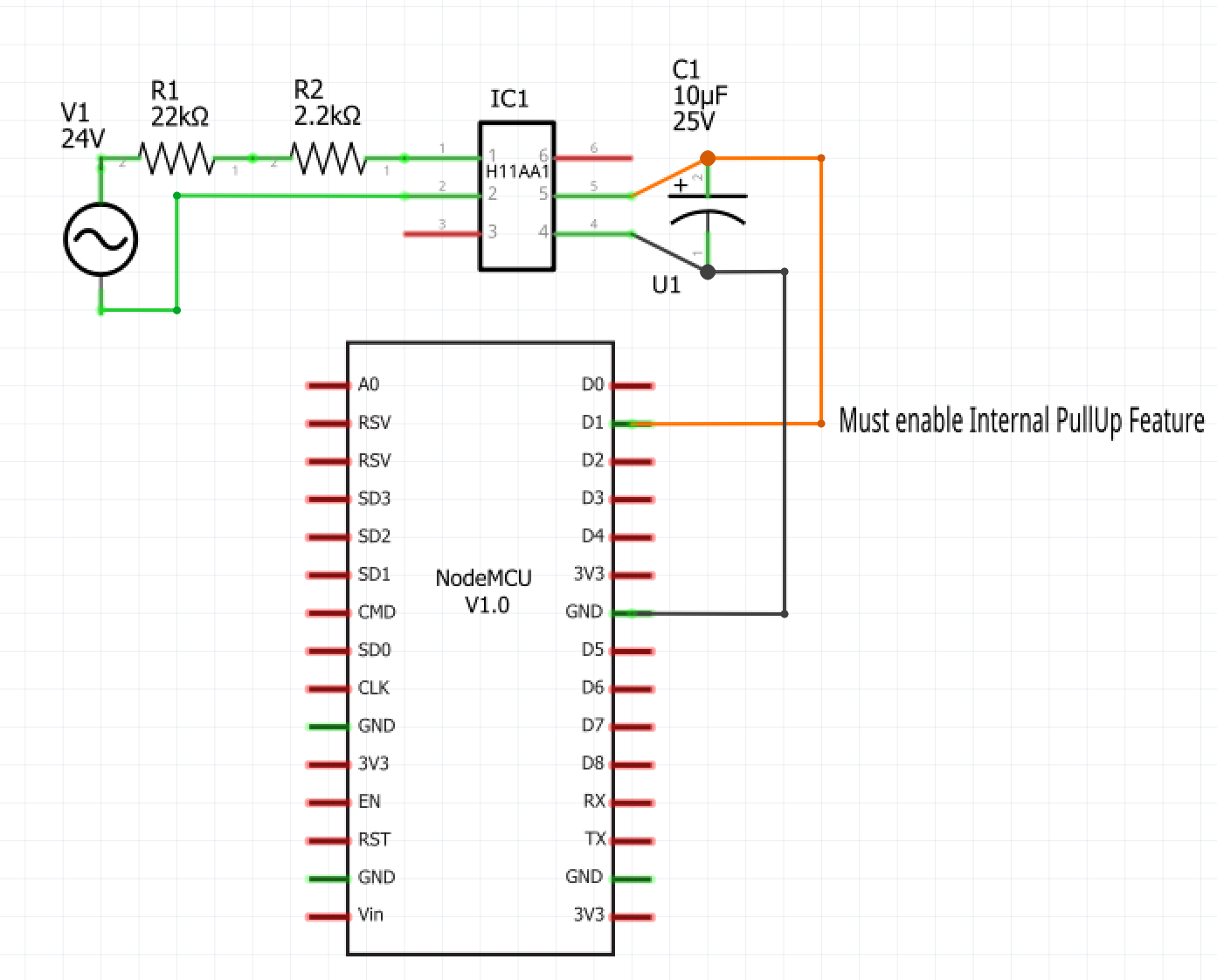
Here is the circuit that I am using. As @JasonJoel mentioned, I found this as well in searching the Arduino forums a few years ago. I sourced the H11AA1 chips from Amazon. I chose the resistance to limit the current seen by the H11AA1 to 10ma. This is within the chip's specifications, and still provides enough current to activate the opto-isolator LED within the H11AA1. The 25V/10uF capacitor on the output was what I had handy from another project. This ensures that the Arduino/ESP8266's digital input never sees the "zero crossings" which would cause the input to change state while AC power is on. I simply wanted the input to be either off or on, depending on whether or not 24VAC is applied.
Hope this helps!