Hey guys looking for any ideas and help in monitoring a bunch of Honeywell low voltage water valves. I have my brother's house that has hydronic floor radiant heating. There are 12 zones in all and all the valves are centrally located. Each valve has a simple Honeywell on-off low voltage 12vac thermostat that controls (energizes) the valve to open whenever it gets too cold in the room.
Instead of installing 12 zwave thermostats which would be ideal but that is cost-prohibitive. I was thinking there might be an easy way to simply monitor the valves 12vac power that would at least tell me whether or not there is heating being asked for at one of the zones. Does anyone have any suggestions on monitoring the status (not analog value but binary on whether there is voltage present or not)
I built something very similar to monitor my standard thermostat low ac voltage outputs. It required some inexpensive chips to convert from ac to dc to make the signals easy to read via an ESP8266 board. Then HubDuino handles getting the data into Hubitat. If you’re interested, I could dig up the information on the parts and draw up a little schematic.
If all you want is on/off it would be super easy to do it with interposing relays, and bring them into digital in pins on an Arduino (and then into Hubitat).
Or do a few resisters to drop down the voltage and do it without relays (although I prefer relays).
Another option might be to look at the SAGE Doorbell Sensors. They can be had in quantity, cheap (on eBay, I think I paid less than $20 for a 24 pack), and are designed to trigger on 10-24v AC.
Happy to help. Let us know how it turns out or what you end up actually implementing. Not that I need something like that but it is always interesting to hear about the different stuff people have done.
I would just mention that doorbell transformers are AC voltage, not DC.
If your heating valves are DC, the sage might not work for you without a step-down/converter (not sure as I've never used one, and can't readily find the specs).
Never mind, you already said they are 12v AC.... Duh on me - didn't read carefully enough.
Yes, if you can find the Sage device on eBay that would be a super easy way to do it!
I had a similar need (sensing heat calls from a thermostat) and someone suggested the Sage doorbell sensors. It didn't work for me. The sensors are designed for very short events, like holding down a doorbell button. They put out multiple ZigBee signals per second for the duration of the heating calls. See the discussion here.
I'll need to recall exactly how I did this. I may need to take some detailed photos of the board I built to see the exact values of the components and the wiring specifics. I know I used a H11AA1 chip, some resistors, and a capacitor to essentially detect the presence of AC power and send the signal into an ESP8266 NodeMCU board. I usually create a Fritzing diagram so I can recall the exact design, but it seems I did not do this for this project.
Also as an FYI, if you Google Arduino 120v detection or Arduino mains detection you will find many circuit designs that have been published on the Arduino forums.
I was looking at this yesterday for another application I have.
In general they all involve an opto isolator (H11AA1 or other - there are many that could work), sometimes coupled with zener diodes and sometimes not.
I still think an interposing relay is easier - although probably not cheaper.
Another concern with adding a relay is the potential current draw from the signal wiring that you're trying to monitor. HVAC systems, which was my target, aren't known for beefy 24VAC power supplies. I wanted to impact the circuit as little as possible, to prevent having the house temperature control compromised, resulting in my WAF dropping into negative territory!
I found my circuit design... working on a Fritzing project now to share it with others, as well as to document it for myself.
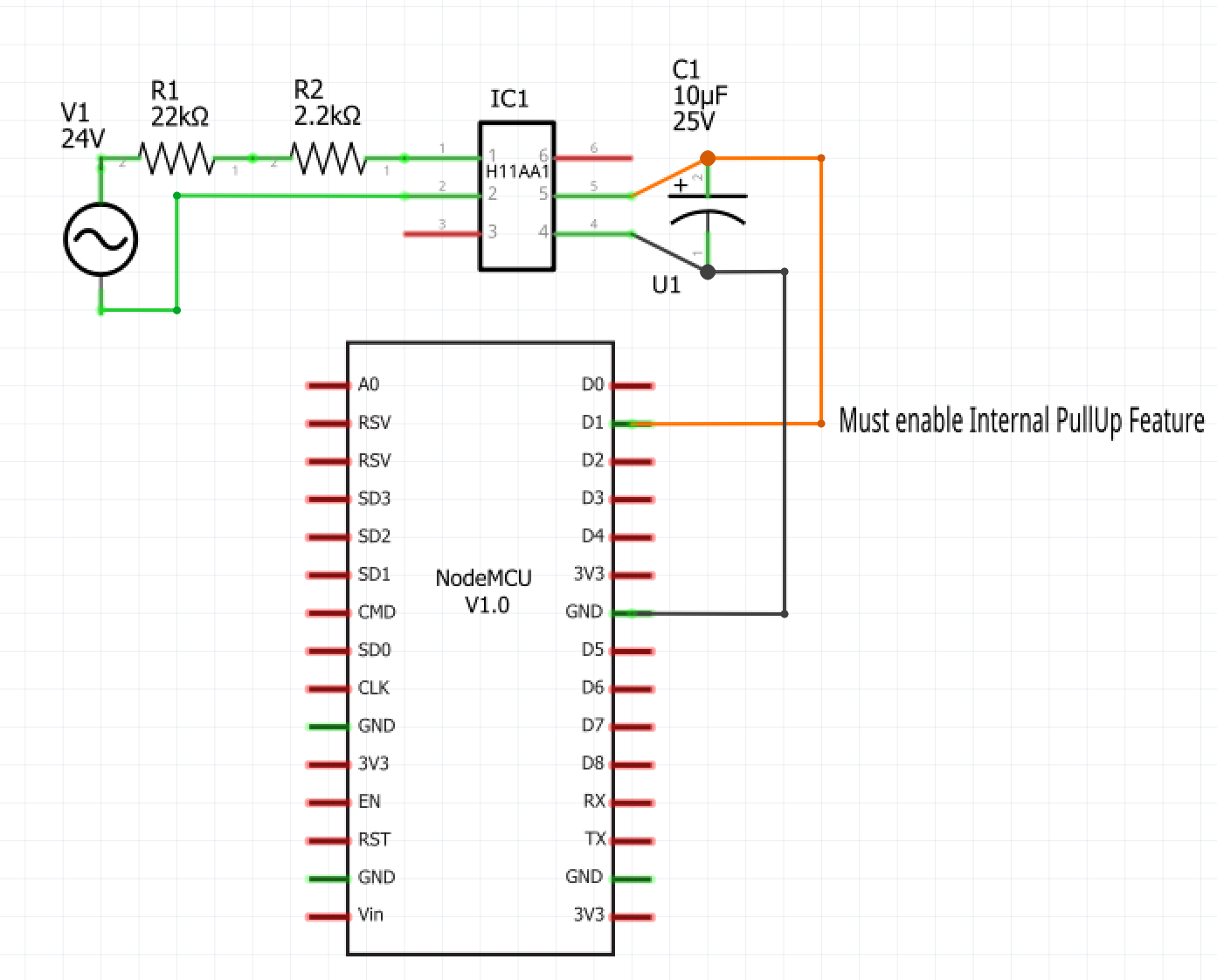
Here is the circuit that I am using. As @JasonJoel mentioned, I found this as well in searching the Arduino forums a few years ago. I sourced the H11AA1 chips from Amazon. I chose the resistance to limit the current seen by the H11AA1 to 10ma. This is within the chip's specifications, and still provides enough current to activate the opto-isolator LED within the H11AA1. The 25V/10uF capacitor on the output was what I had handy from another project. This ensures that the Arduino/ESP8266's digital input never sees the "zero crossings" which would cause the input to change state while AC power is on. I simply wanted the input to be either off or on, depending on whether or not 24VAC is applied.
I'll take you up on assistance getting started with HubDuino. I'm afraid I got stuck on something pretty basic, which makes me a little embarrassed to have to ask. I am an experienced C programmer but totally new to Arduino and its development environment. I haven't figured out how to get your libraries downloaded from GitHub and loaded into the Arduino IDE so that sketches can access them.