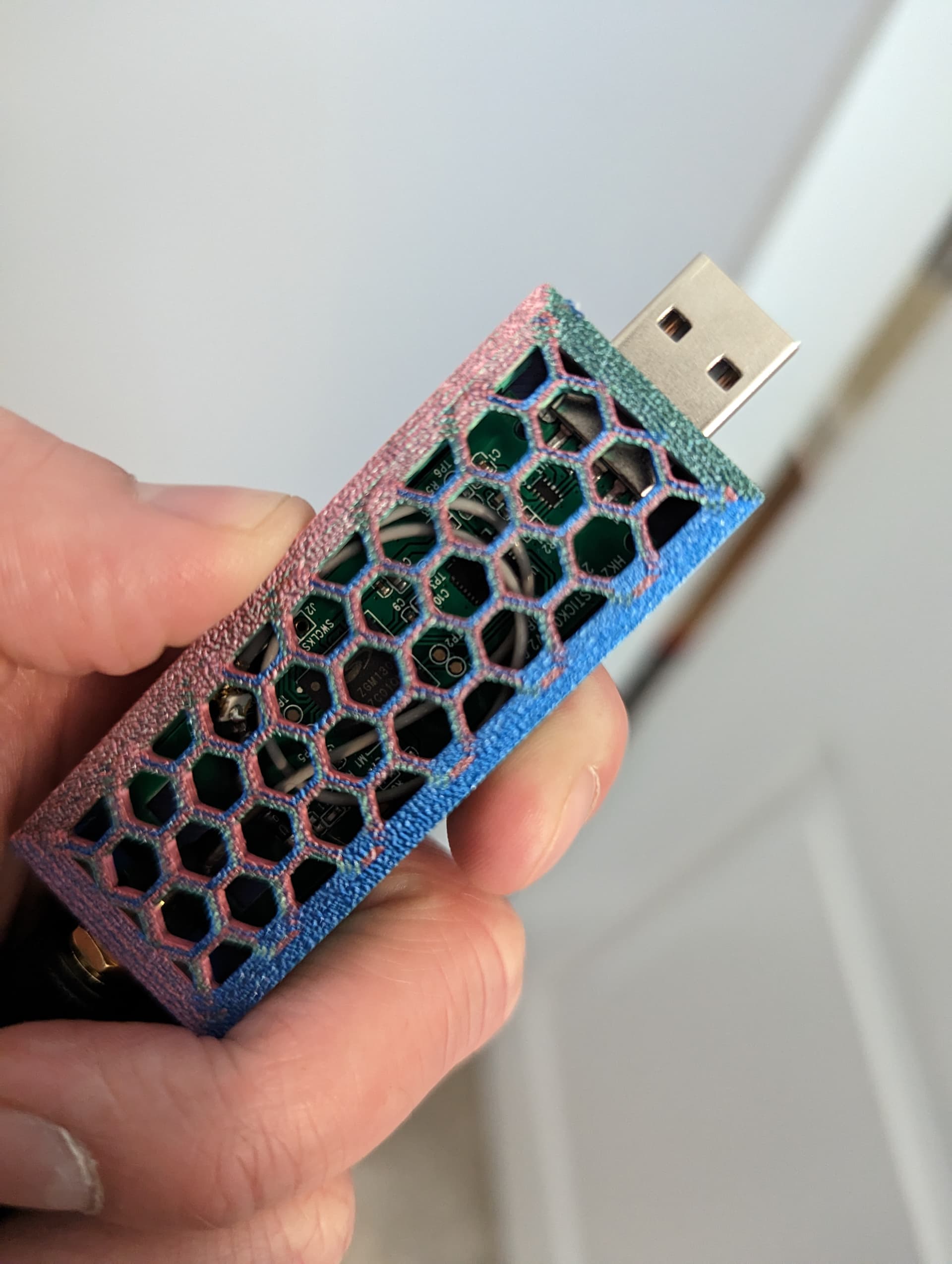
Curious if someone smarter than me in this area has any ideas. I have a Zooz Z-Wave stick that I was curious about swapping to an external antenna. Cracked it open and they're using a coil antenna with a single connection. My idea was to solder on a U.FL to SMA connector, but was unsure if I needed to be making a special consideration for the antenna. A quick Google says the ground path really only comes into effect for 1/2 wavelength antenna, so maybe a full length would be it?
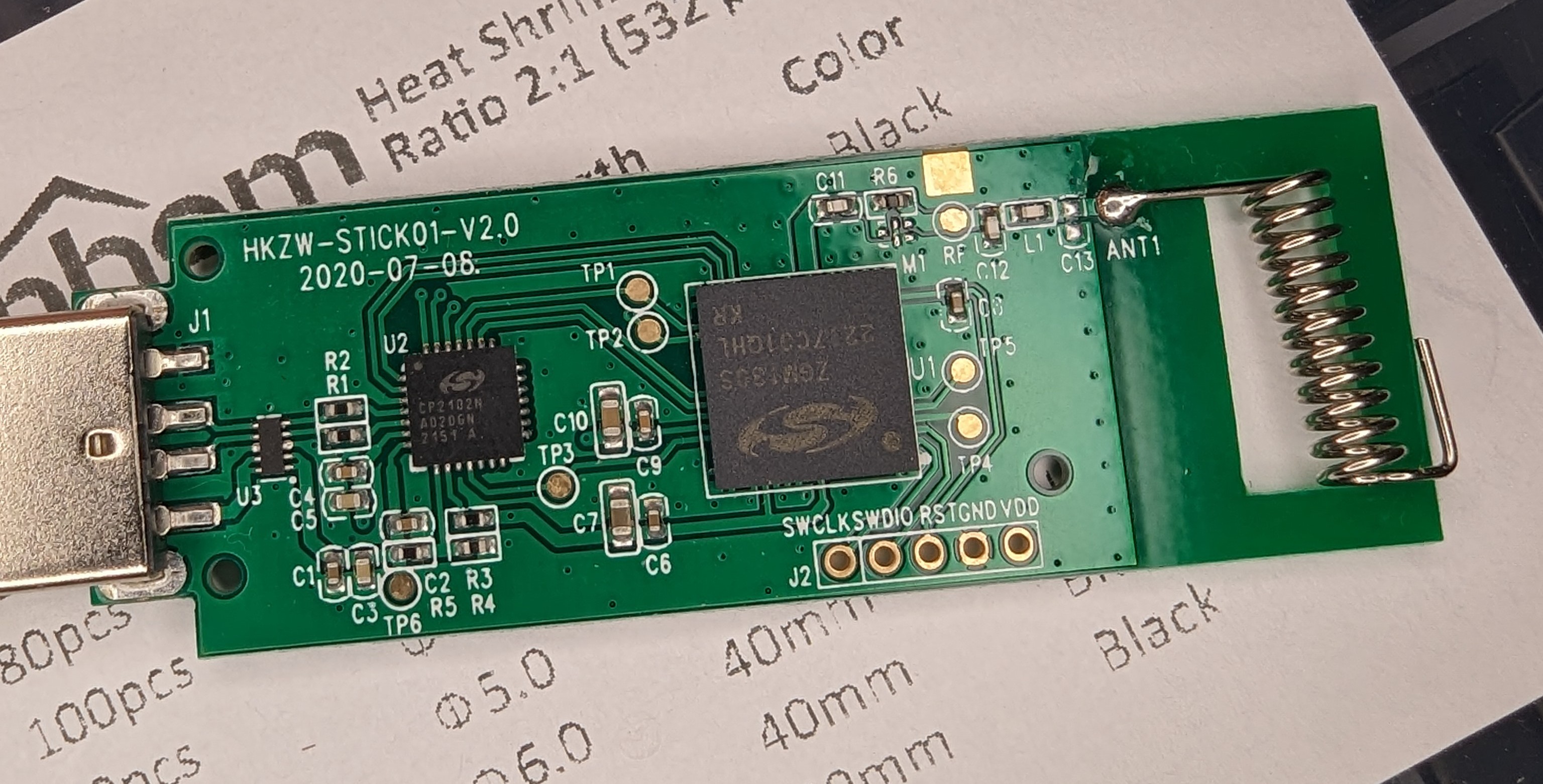
just a guess but don't those two pads look like a place for a surface mount U.FL connector?
1 Like
You might be right. Ooo...I also presume if so, then it's a switched circuit so I don't even need to remove the coil antenna.
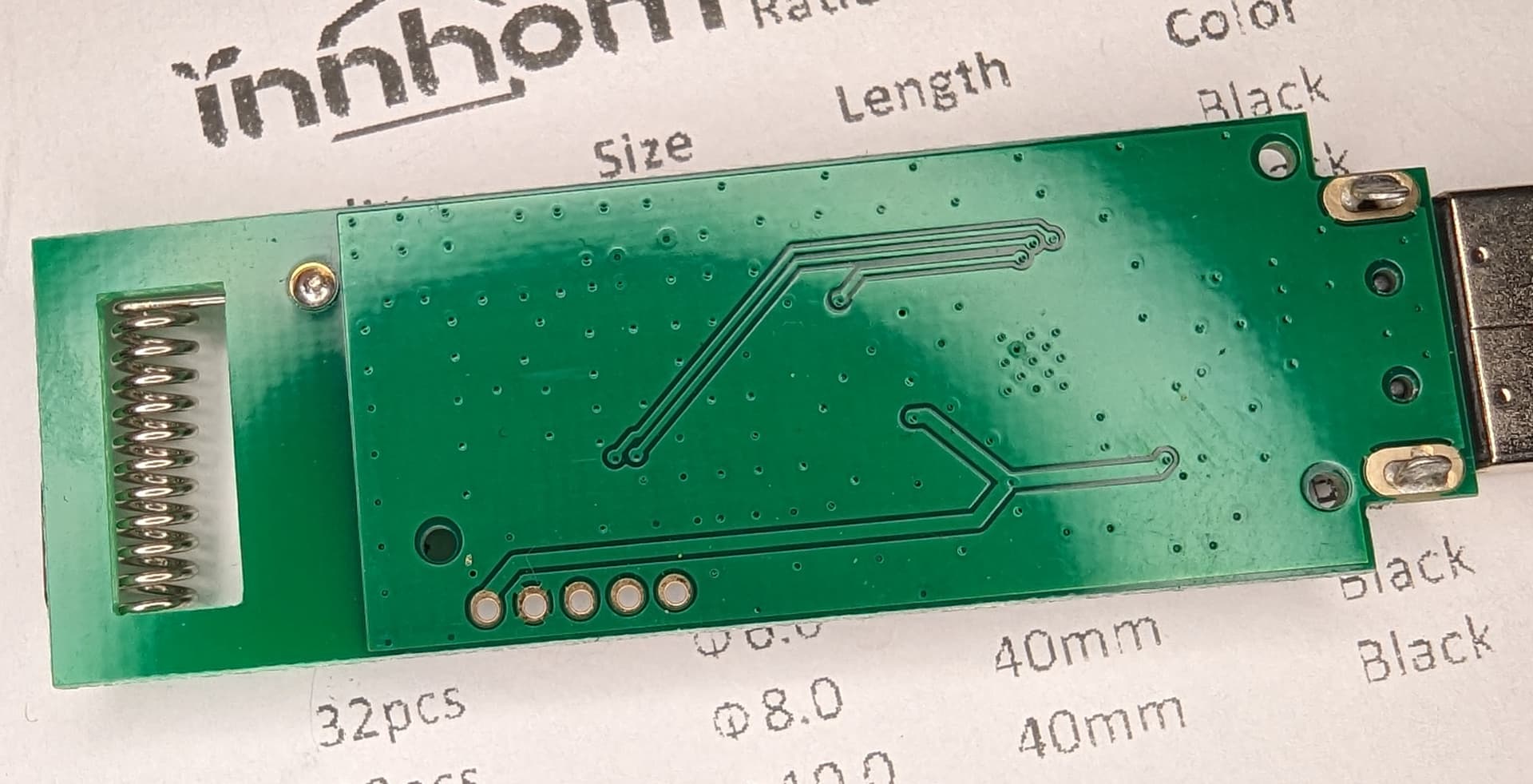
Doesn't look switched to me, just a 50ohm matching circuit from the chip then another to match to the coil antenna.. but that's just wild guesses really.
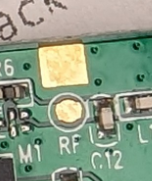
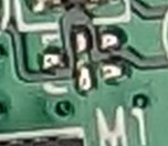
The more I look, the more this looks like U.Fl:
My guess is that you'd want to remove the coil antenna.
1 Like
Thanks man!
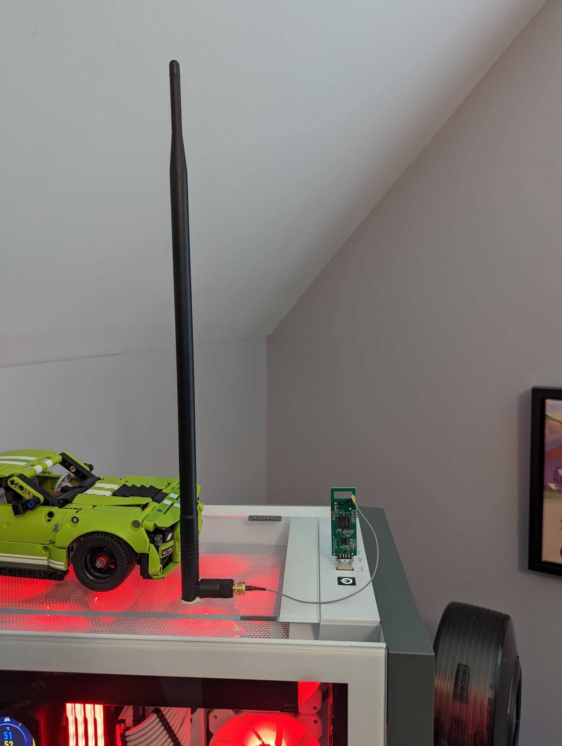
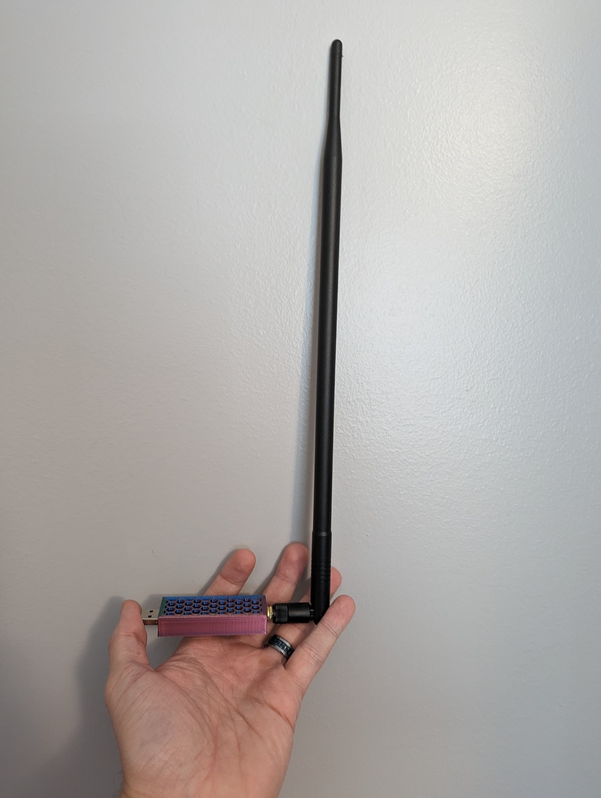
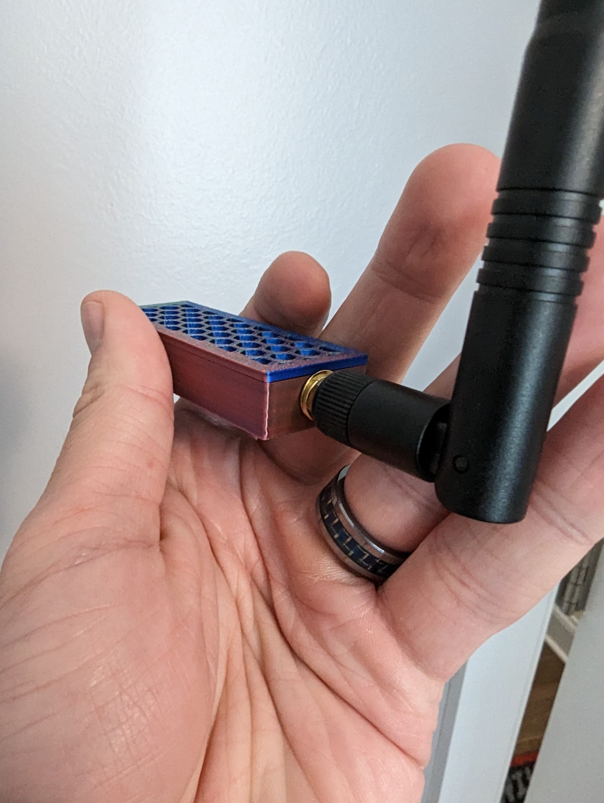
Got a chance to test this out. I opted to add a lead wire vs having to heat the coil antenna to get it straightened out. I also wanted to keep the coil intact in case this little experiment didn't pan out.
Using a full-wave antenna I was able to get some nice bumps in signal.
Coil antenna:
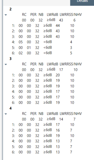
Full-wave:
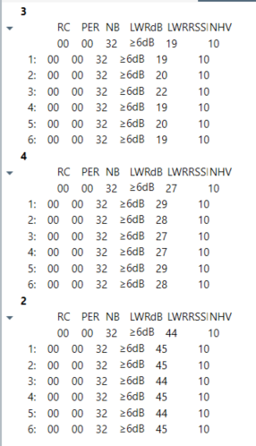
Device 2 is a ZEN21 that's about 12' from the dongle in the same room.
Device 3 is a ZEN22 on the opposite side of the house.
Device 4 is a GE Fan Switch in the same box as the ZEN22.
I just realized all three devices are 500 series chips. Probably should have tossed in a 700 for good measure, but too late now.
2 Likes

This topic was automatically closed 365 days after the last reply. New replies are no longer allowed.