Yeah I didn't mention it but I re-wired to get my neutral down to the nearest switch (to use the Lutron).
I've found FB Marketplace is the best place to get rolls of NM cable - just don't ask too many questions. 
Yeah I didn't mention it but I re-wired to get my neutral down to the nearest switch (to use the Lutron).
I've found FB Marketplace is the best place to get rolls of NM cable - just don't ask too many questions.
For anyone researching a similar issue, I just wanted to let you know that there was an issue with the initial beta release hardware that's described in the changelog for the ZEN51 and ZEN52 model. It has been addressed and as long as the devices are installed correctly per the diagrams, they work well.
Measuring Voltage on electronic controllers is usually not the best diagnostic path, especially with devices that change their electrical behavior depending on advanced settings. But just to clarify - the input (switch leg) requires 120 V, it's not isolated from power like the output part of the ZEN51 relay. This is because the ZEN51 model is not like our ZEN16 relay with dry inputs and outputs. It's designed for different functionality, with lighting applications and 120 V monitoring (of pumps or motion lights) in mind. I hope that clarifies it but feel free to reach out to our support with any additional questions.
The one I tested of course was an older 1.10 (on the back) model. I have one that is a 1.30 marked on the back so I will try that one out tonight and it sounds like that should work!
That’s good news. I have a 1.10 hardware version that wouldn’t work in the location where I needed it, but I have updated it to the 1.30 firmware (on my bench, not installed). Will the 1.30 firmware on the older hardware give me any improvement or should I just buy a new 1.3 hardware version?
Thanks
It was a hardware fix, so you would need the new hardware. I am going to put one in tonight and I can confirm if it works where the old one would not. Both of mine are updated to 1.40 firmware.
That's great to hear the 3way issues have (potentially) been resolved. Can users with existing older ZEN51/52's be offered replacements? As it stands the ones I purchased cannot be used as they do not work as advertised. Feel free to send me a message directly. Thanks.
@nibyak @slip1n1fall
Success with the 1.30 hw, wired exactly the same and worked right out of the gate. Made a slight customization to the box so it could sit outside of it for easy access.
New hardware is needed if the 3-way isn't working on the wall switch side. I'd recommend checking the wiring with our support team and once we verify everything looks good, we can replace the device for you.
Yes, absolutely. If the device doesn't currently work in your set-up, just get in touch with our support to request a replacement. We will always need your order number and images of the wiring to make sure the device is installed correctly.
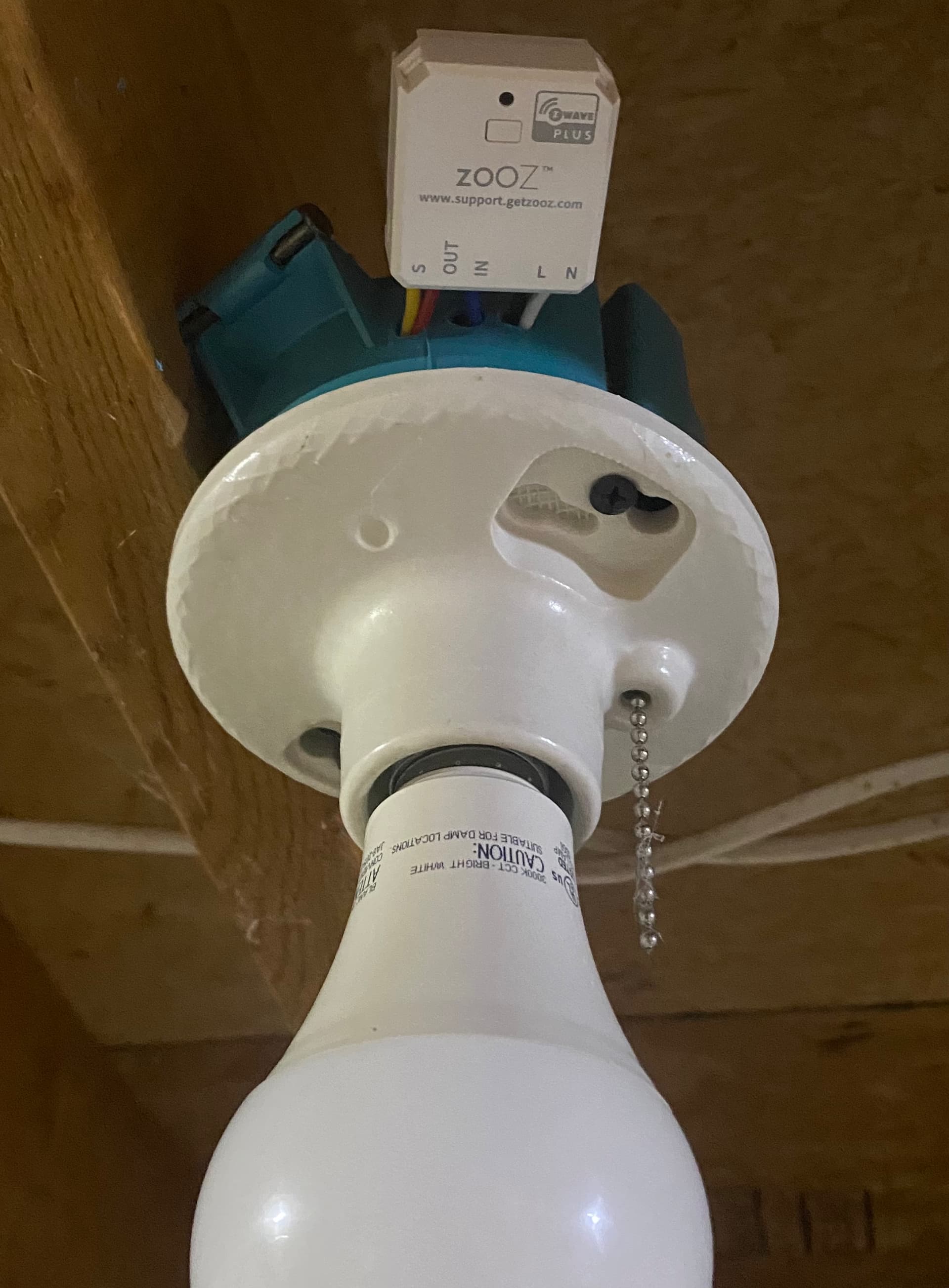
I just tried installing one of these in my garage. The goal is to get a switch that doesn’t have neutral to turn on/off a light fixture (through the relay) to trigger a separate smart bulb to turn on/off as well. Ideally this is all done via the physical switch like a normal light.
Since I’m installing this at the fixture where neutral is present, I’m wondering what else I have to do to be able to turn on the relay via the dumb switch? I was able to add the Zen51 to Hubitat and control via the app. I can turn off the relay from the physical switch, but nothing happens when I try to turn it on from the switch. Hubitat controlled on/off works with the switch in either position.
I reached out to Zooz support, but thought I’d mention it here to for anyone else. So close to getting this working!
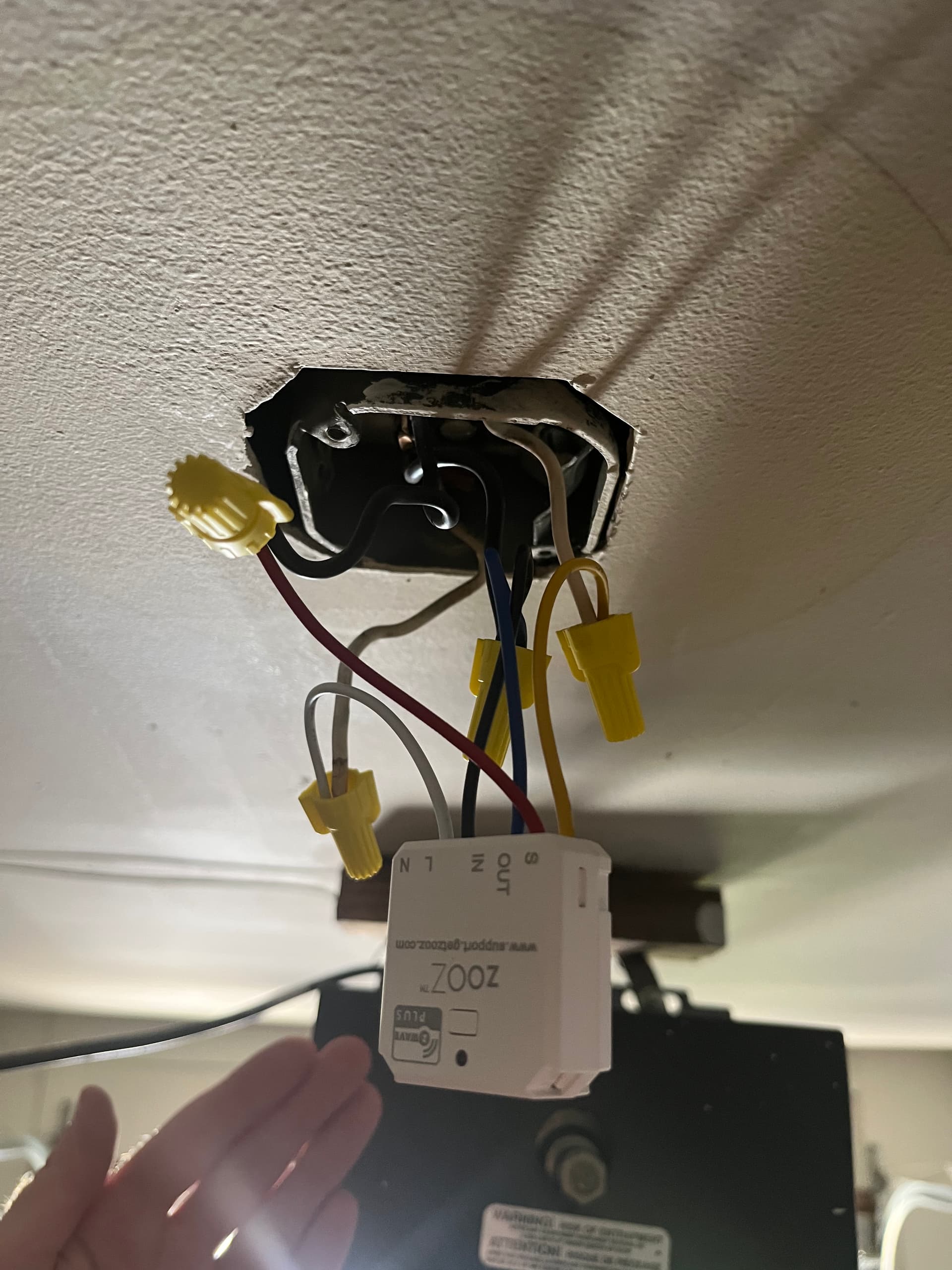
I would assume you have a single two wire going to the switch? Looks like the white is wired to the yellow S which is good. On the same wire is the black tied in with the black hot bundle? This would then send 110v to S when you turn it on.
I wired up a 3way with the same setup, works great.
Blue IN should be with the black hots, and red OUT goes to the load (light)
I think I have everything wired correctly except that the white of the two wires going to the switch is no longer paired together with black like before. I was thinking that was what was missing. I was thinking maybe the relay would handle that.
Edit: Re-reading, I think I do in fact have everything wired correctly. For the single two wires originally going to the switch, the white is with S1 and the black is with the black/blue bundle. Turning the relay off from the switch turns the relay off, but turning the switch on does not turn relay back on. I will try by having a separate line going from the hot black bundle to the s1/white bundle, but I don’t think that’s necessary?
No that would not work, sounds like you have it right.
What FW version is stamped on the back and what FW is it on now?
Also, what setting do you have the switch set to? You probably want it on the default On/Off setting.
How long is the wire run to the switch, you may some induced voltage which effects the original hardware marked FW 1.10 on the back.
I upgraded to FW 1.40, but still need to do the suggested power cycle. Hubitat reports 1.40 as the firmware now though. It’s probably no more than 15ft from the fixture to the switch.
Need to know what FW is printed on the device. There was a hardware fix which is printed FW 1.30 on the device. Not sure what you mean by "still need to do the suggested power cycle".
This is a single switch or a 3-way?
Sorry 1.10 on the device back. It’s a single normal switch.
For the built in Firmware Updater, it says to power cycle the device for best results.
The 1.10 HW is the original, but it should work fine with your run, I think over 15ft is pushing it. But since you can turn it off and not back on that is more indicative of a wiring problem I think. I think it mostly only was a problem with 3-ways also.
I only see the IN and OUT tied to one other wire which I assume is the hot feed. Where is the switch leg getting its hot power? The switch leg would have two wires, the white you are using as the return, the black would be the feed, the black should be connected to constant power. Both white and black should be connected to opposite mounts on the switch itself (same as it should have been prior).
Also where is the light, in another box? Light should have Neutral tied into the Neutral bundle, and hot should be connected to the RED/OUT
It almost looks like the black/red combo and the white/yellow are both the same wire, and I don't see any other wires. So still confusing on your wiring.
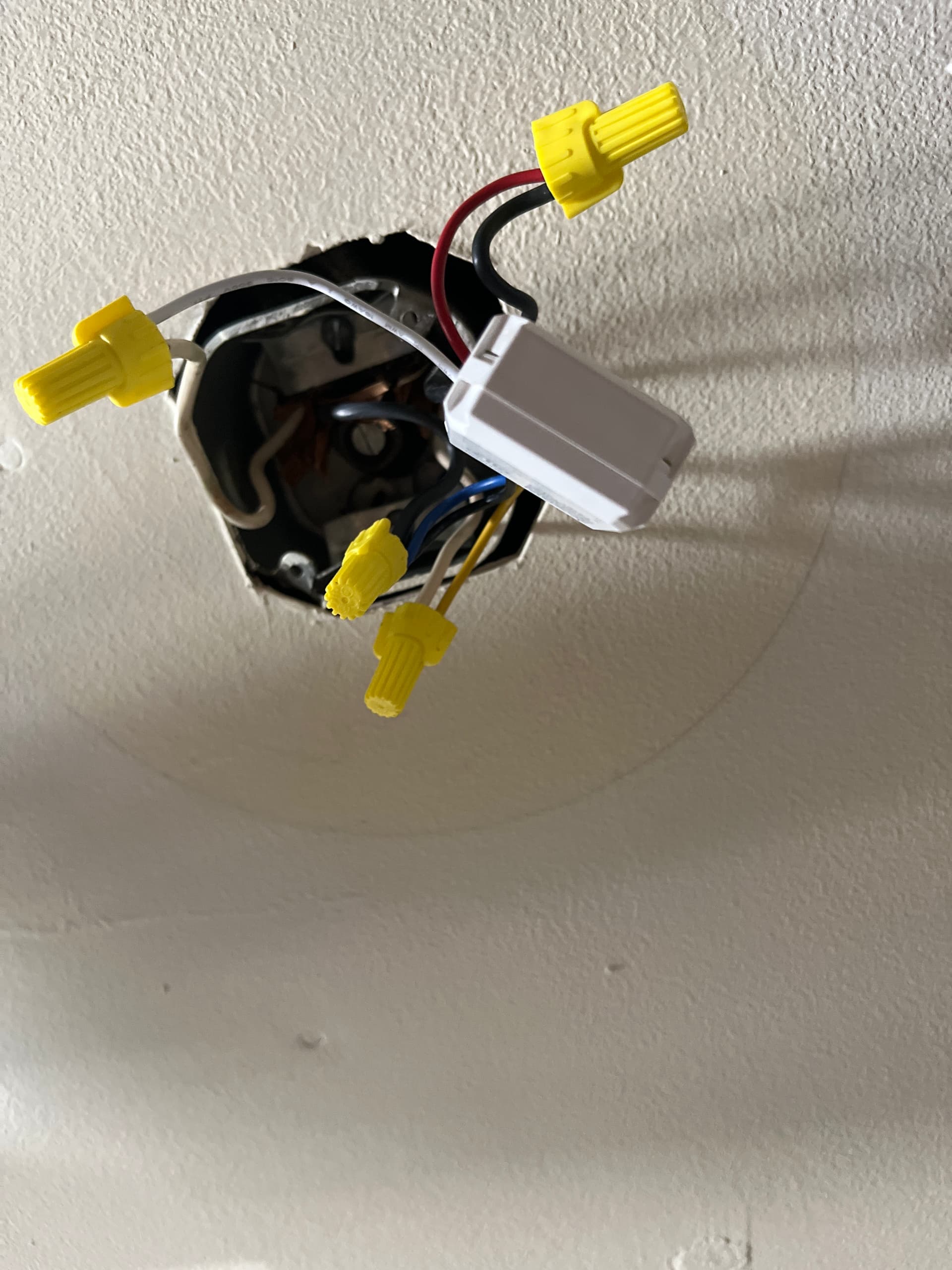
I had removed the light just to make sure power was properly getting to the relay. Here’s some more photos of the wiring. I’m no electrician, but maybe there’s the potential I swapped the black that was going to the light fixture with the black of the black/white pair.
I cant really see where the RED/Yellow eventually go in those pics.
Where are you connecting the light fixture in there? If you have it removed the Red should be capped with nothing on it.
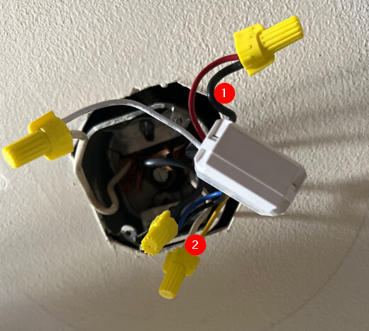
If 1 and 2 as I marked are both going to the wall switch which is what I suspect, that is the problem.
2 would be correct in that case, but 1 would need to go in the hot feed bundle, and the red goes to the hot on the light fixture.
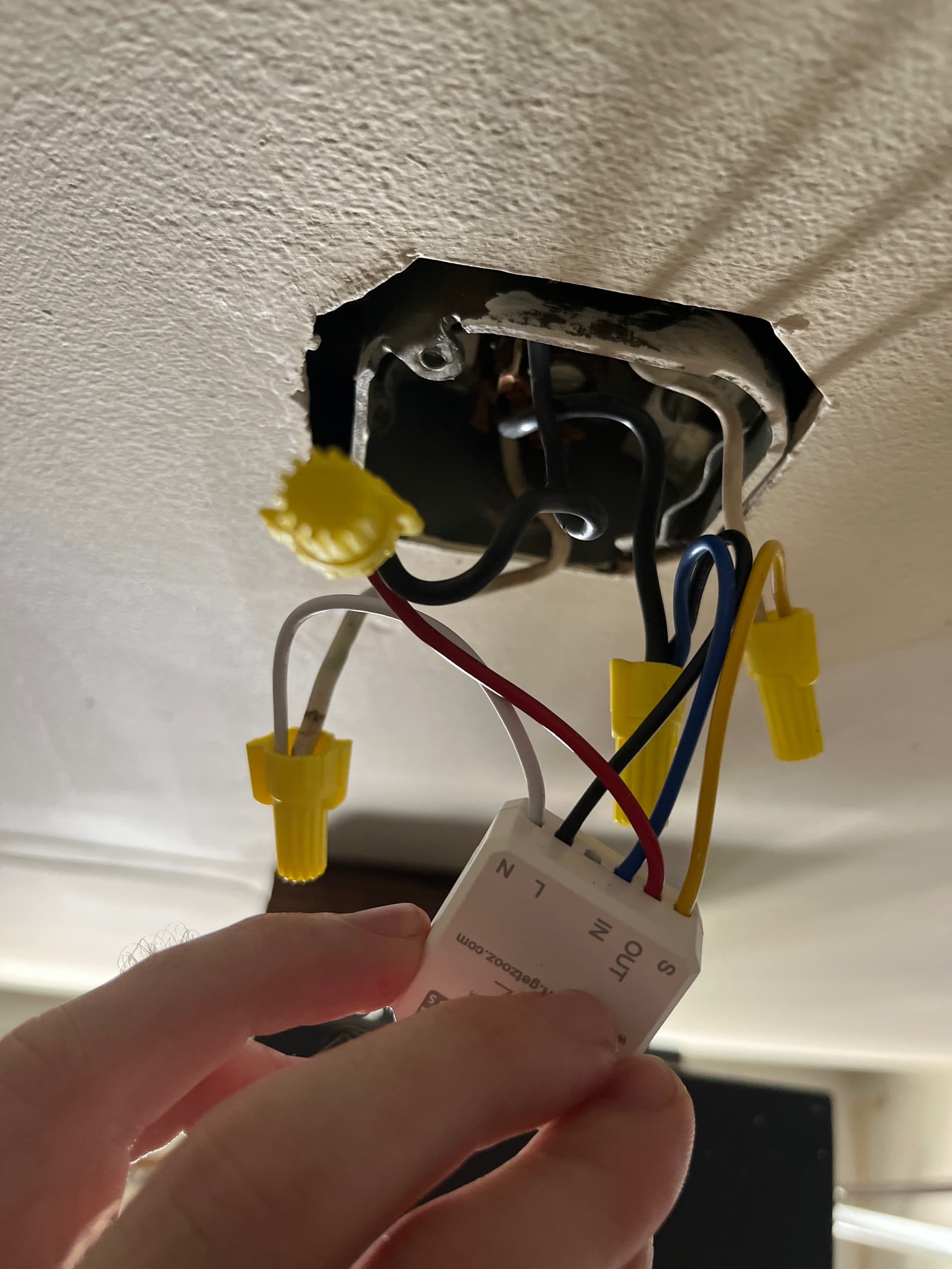
The way I have it:
The blue/black bundle goes to the switch (3 of 3 wires pictured)
Red/black would eventually go to the light fixture (2 of 3 wires pictured)
Yellow/white goes goes to the switch (2 of 2)
Neutral whites to to light fixture (2 of 3 wires pictured)
Ohhhhh I see. Moved the black that was with red to the black hots. And it works I think?
Download the Hubitat app