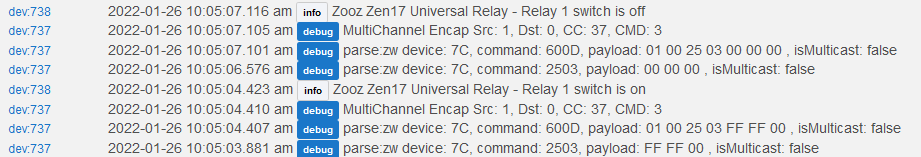
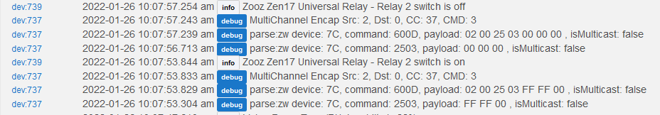
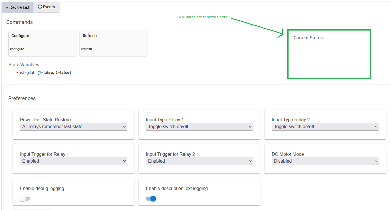
I just received one of these and can't find a way to determine what the input state is. The parent driver has a field for "Current States", but it is not updated regardless of the trigger type: either S1/C or C/VC. I excluded and reincluded but can't get the state to display any input. Both inputs send the changes to the hub:
Did I miss something when I installed the Zen17? I need to detect when the input is triggered so that I can (through a Rule) decide whether or not to close the associated relay.
Would suggest taking a look at the Device Manual - on the second page, under Customizing your Universal Relay, parameters 2 and 3 are what you're looking for, I think. Based on my reading of the doc, adjusting this should trigger creation of relevant child devices for the connected sensors? Don't know for sure as I don't have one of these to play with....
I've tried various selections for "Input Type Relay 1". They create appropriate child devices for "Zooz Zen17 Universal Relay - Relay 1" which all correctly trigger when the input is tripped (S1/C). The problem is that parent device ("Zooz Zen17 Universal Relay") doesn't report that the input has been triggered (ex: On/Off, True/False, 1/0, Open/Close).
Yes I have. Waiting for a reply. I contacted them before I purchased the relay and outlined my intended usage. The told me
"You can certainly provide the 24V AC signal to the C-Vc input on the ZEN17 Universal Relay. At this point, the device will get info in the hub dashboard about 'call' - it will depend on the input set. It could be ON/OFF (default ) or another sensor. Now, R1 will change the status , so it can be used for start/stop anything ( open/close another circuit )."
That led me to believe I would be able to detect when C-Vc input saw 24VAC and I would be decide whether or not to close the relay. Unfortunately it's looking like I'll have to detect the relay being closed and then decide if I want it to stay that way. From the logs (first post above) it looks like the info is being sent, just not made available in the parent driver. It would be unfortunate if that's the case.
I'm not sure I understand... If the child device reports the relevant event, why is it necessary to replicate that event in the parent device? Seems like that would be a duplicate effort for the hub...
Or am I missing part of your use case, that prevents writing rules that trigger on child device events?
If you want to be able to use the events from the inputs, without automatically triggering the relays, then I believe you should change the settings for "Input trigger to Relay N" to Disabled
24VAC applied to the input (C-Vc). When this happens I want to be able to decide whether or not to close the relay which will apply 24VAC to another device. As it is I only find out that the relay (Child device is tripped) meaning that the input voltage was applied. It's not a critical application and I can just turn off the relay if I didn't want it on.
It's not really duplicate information since the relay can be disabled (Parameter 10). The manual says:
Input Trigger for Relay 1
Parameter 10: Choose if you’d like the connected
input (switch) on S1 C / VC C to trigger the load
connected to R1 or if you want to use the input
reports for monitoring only and separate the
output from the input.
So, you're saying that if I disable "Input Trigger for Relay 1 ", exclude and reinclude, the "Current States" will be populated? Okay, I'll give it a try.
Not sure about where the states will be reported - I certainly won't guarantee on the parent/master device... But yes, based on your described use case, I think that is the setting you want.
The manual specifies to exclude/include for values 4-10, on parameters 2 and 3.
This sounds like a driver issue, setting a default value without reading from the device.
They would be the authoritative source of info - likely collaborated with Hubitat on any built-in drivers.
One item I could suggest to provide more detail to this community, is a view of each child device created under the master/parent. The exclude/include language on params 2-3 suggests to me that there may be some logic checking these values and creating child devices accordingly during discovery...
Zooz got back to me and confirmed that the parent driver is supposed to report the state of the inputs. I have two hubs and tried the ZEN17 with my second one, but no difference. It doesn't report the state of the inputs and disabling the relays (in the parent driver) still has no effect. I can always try the "Basic Z-Wave Tool" driver to change Parameters 10 & 11, but I'd like to get the input state reporting first.
I know my first go 'round with a ZEN16/17 took a bit of effort as well. I seem to recall that there is a way to set some of the parameters outside of the driver interface. For example, pressing and holding the button for 5 seconds puts the unit in "Garage Door Mode." I think I ended up pairing it a handful of times (and a couple of factory resets) before I got it all set where I needed it.
Now that I'm thinking about it...here's how I remember it. Pair the device. Set the "mode." Unpair. Pair. See parent/child devices created and test them. Scratch head because its not doing what I want. Unpair. Factory reset. Pair and repeat. This went on for 3 or four iterations until I finally got the correct parent/children to appear and the behavior I wanted.
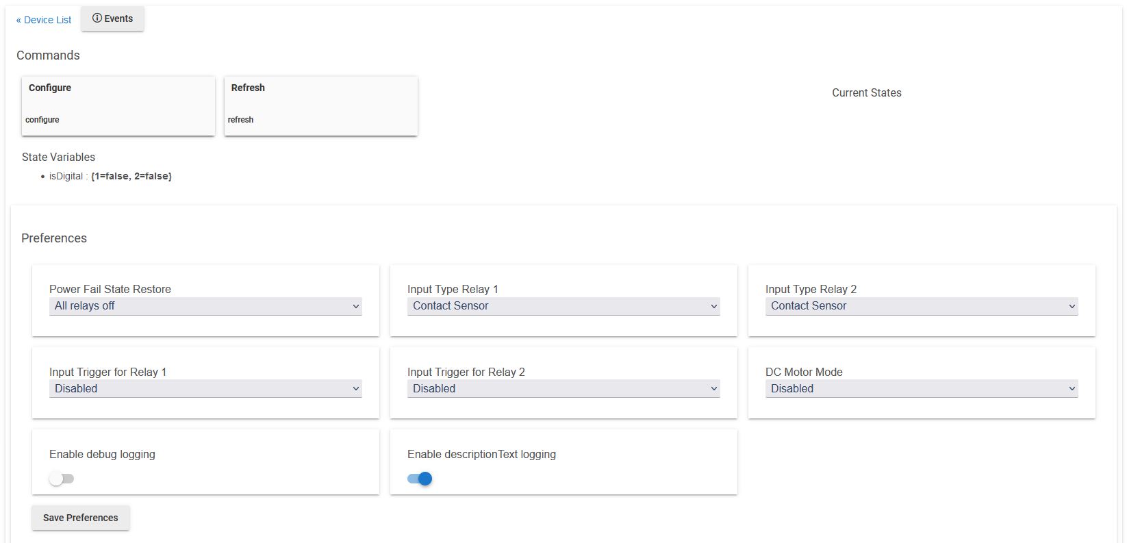
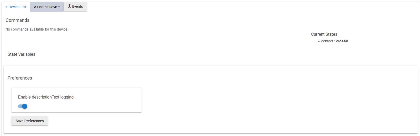
For the Zooz Zen 17, you should end up with one parent and four child devices. The child devices should be two relays and two contact sensors. A screenshot of the parent and a contact sensor child are attached below. Note that the status of the contact sensor only appears in the child device.
Yes, mine looks similar to yours except that I left the child devices (the relays) as the default "Toggle switch on/off" which is sufficient for my application.
Question: your parent driver has both input triggers disabled. How does your contact sensor ever open? With no input trigger I don't see how the relay can respond?
I changed the driver to the Basic Z-Wave tool to confirm that enabling/disabling the "Input Trigger for Relay n" actually works. It does. However, setting these parameters (10 and 11) to 0, does not actually disable the input trigger. An input (S1/C or C/VC) still triggers the relay. So getting an input State report in the parent is moot since the input and relay apparently cannot be disconnected.
This could be the problem. Each time the input connected to VC/C changes, the relay will toggle regardless of whether or not the input is "on/open" or "off/closed." In this configuration it may not show the state of the input because it is irrelevant to the operation of the device (at least according to Zooz and their driver).
The contact sensor input is wired to a physical contact switch on my garage door. The state shown in HE shows the state of my garage door (open or closed). The relay state (on or off) is controlled by rules.
As dylan.c said, they most definitely can. My Zen17 setup (which is same as dylan.c's - we both have our Z17 set up the same way for our garages) depends on that capability and it works great.
The Zen16 does not have this decoupling capability.