Ok. So I know there’s a ton of posts about garage door openers and zen16 integration, but I can’t find any that help to wire just a regular garage door opener. Perhaps I’m just without shame for asking what might be a simple question.
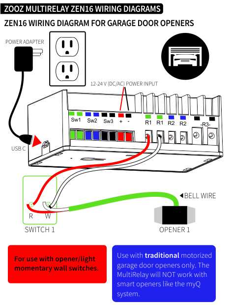
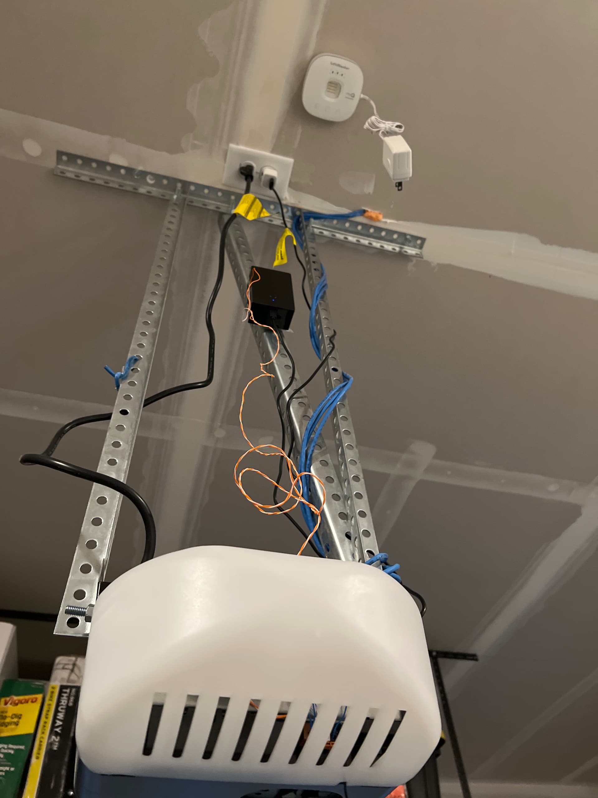
Based on garage door opener schematic provided by Zooz support pages (attached below) it looks like I need to put this lovely black box somewhere near the momentary wall button in order to wire it correctly.
The wires from R1 go to the terminals on the button, which is also where the wires that operate the garage door are currently connected.
I think I understand why -because the same momentary close-circuit signal that is set from a physical button press also simulated when controlling from the zen16, and in-turn a physical button press will cause the zen16 to report open/close respectively
But I’m trying to think of an alternative method that results in the zen16 being placed somewhere near the opener unit, out of sight. - I can just hear my wife now - “what the he:ice_hockey: is this ugly box doing mounted right above the GD GDO button!” - sorry @agnes.zooz these are not my words, I think the zen16 is a marvelous piece of equipment!
Also, might be good to mention the original installers used cat-5e cable (only 2 strands), not bell wire, although that doesn’t seem relevant.
More relevant is that the wires are hidden in the ceiling and wall to the switch (new construction home).
TLDR: Before I go and render my GDO inoperable, is there any reason I can’t just splice the bell wires into r1 at some point before the wires reach the ceiling unit?
Please excuse my crude re-drawing of the original!
Thanks for hopefully a simple answer, but I’ll accept complex if you feel like schooling me!
Edit: yes, I just marked solution on my own reply to my own post.
Original reply:
OMG 💡! I have extra wires to work with
I think I just figured it out. I must’ve wrote the piece about cat 5e being used as irrelevant, knowing that it stood out and might be useful to share for some reason.
Well, 20 min later, I’m just racking my brain again and  ! If only one of the pairs from the cat 5e is being used for the switch to the GDO, then I essentially have 3 other pairs of wire already fished through the walls! AMAZING!
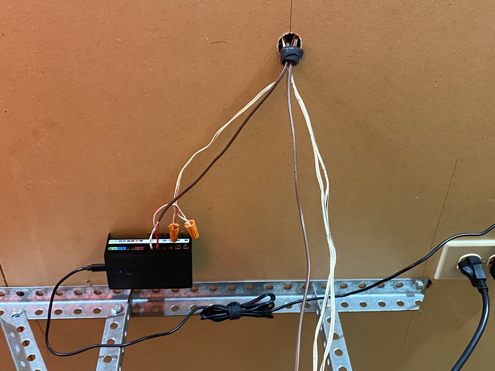
So I’ll just hook one of the pairs up to R1, plug it into the outlet that’s up there and command strip it to the ceiling, then just double up on the button on the other end with the second pair.
I still must say thanks to the community for being a great sounding board even while no responses yet!
*also a shoutout to the electricians who wired this up, even though they most likely used it because they had it.
Hoping this helps someone remember to try to make use their existing environment before trying to think of masterful ways to complicate things!
Now on to thinking of other fun things I can do with the 2 extra pairs of wires, not to mention the additional sets running out to each if the safety laser thingy’s. - I welcome the creativity that some of you who are more experienced with home automation!
1 Like
I think you figured it out, but you don't have to put the zen16 by the button, you can put it up at the unit itself. The Zen16 relays are in parallel with the manual button.
I have one of these in my shop and it is located by the buttons, My shop has two doors and the buttons are brought down side by side on the wall. So in my case it made sense to mount it by the buttons. Also it's my shop and I don't have to worry about what my wife thinks about it. If I wanted to mount it up by one of the openers itself I would have to either get two of them or run wires from one to the other through the attic. The attic in my shop is not somewhere I want to be crawling around in. I'm getting too old for that crap.
2 Likes
Thanks for the info on the relays. I’m still a bit fuzzy on the theory behind it. If I just wired the zen16 anywhere in the line, then my logic seems to think there would be improper signal translation and possibly randomly opening/closing of the door.
Since the Zooz is sending the signal out if using Zwave commands, then wouldn’t I want it to be before the switch (as pictured). That’s what hung me up in the first place. And why I’m glad I already have a run heading to the switch. But if I didn’t have that, I’d pretty much be asking this question. Thanks!
You can wire the ZEN16 per your "alternate" diagram you made as well. That's how mine is wired up mounted to the ceiling by the opener. On old openers the wall button is just a dry contact so you can hook the ZEN16 anywhere as long as it opens/closes the same contact as the button.
I played around for hours trying to get it to work right with the button on SW1 and only the opener on R1, and it did work but I lost the little LED light on the button and mine also has another button to manually turn on the light which did not work this way obviously.
2 Likes
Electricly, it’s the same thing. You are shutting a switch for half a second. Either with the doorbell switch or the zen16. Same signal goes to the GDO.
The zen16 just happens to be able to know that you have pushed the doorbell button instead.
So, if I was in your shoes and had 4x pairs of wires. I would pick 2 more wires at the doorbell and connect them with the 2 already installed.
Find those same 2 new wires on the other end at the GDO end and install them in the zen16.
Then plug the zen16 in the other plug of the outlet that the GDO is powered by.
Which is exactly what Zooz drawing shows.
2 Likes
Let us know if everything is working well @jwvincent2!
And just in case anyone else is researching this topic, we have detailed wiring and programming instructions for the ZEN16 acting as a garage door opener on Hubitat posted here.
Interesting. I think I failed to mention that my GDO physical button is similar to yours in that it also has a separate button for control of the light on the motor. I mistakenly implied that I had this by only including the schematic that Zooz provides for this type of button setup.
Just to clarify @jtp10181, you’re saying that the “alternate” picture I provided will not allow for control of the secondary button that controls the light?
I intend on doing as @CHoppopotomus mentioned as it follows the Zooz instructions exactly.
That being said,  , at this point I’m just curious about how the secondary button even works from a basic electrical perspective since there are no additional wires used to send signals from this button press. Logically (for me at least) it seems like more wires would be needed to send signals to different parts of the machine but that’s obviously not how a GDO works.
Does the secondary button for the light just send a slightly different voltage to the GDO to cause only the light to turn on and NOT trigger an open/close?
Very interesting. Thanks for indulging my quest for knowledge!
I would guess the secondary button sends some sort of special digital signal across the wire that can be differentiated from simply closing the circuit. Possibly as you suggested a much lower voltage than expected so that it can tell the difference without a doubt.
No, it should work. I was saying I tried it another way where the button connects to SW1 and could not get the led or extra buttons to work that way even with some creative wiring.
I believe mine is wired up with your alternate method. Brown goes to the operator and white is the original from the button. They are both connected to R1 and this each other at the same time.
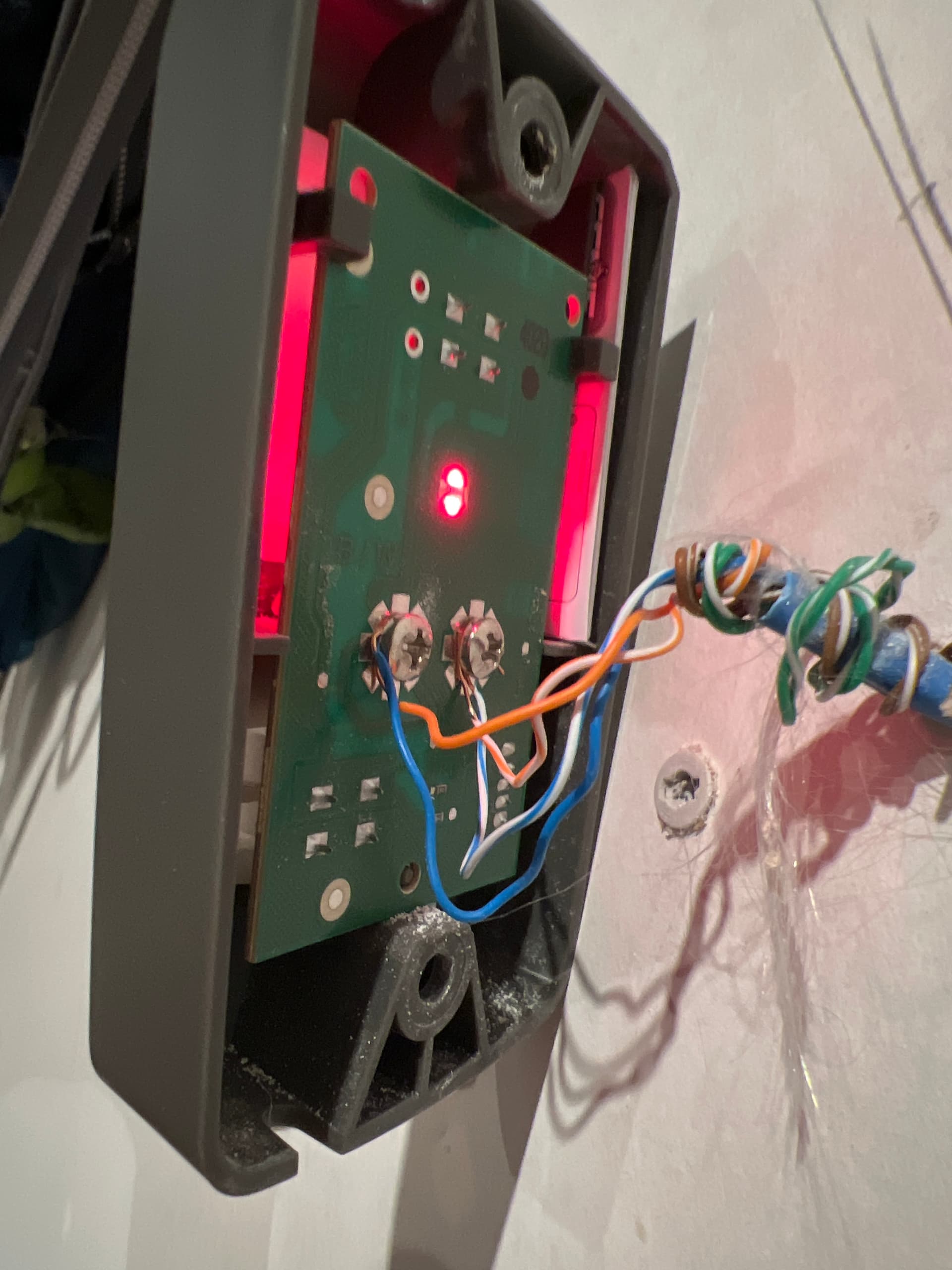
I for one would be curious to see how the oem switch is wired. With one pair of wires or two.
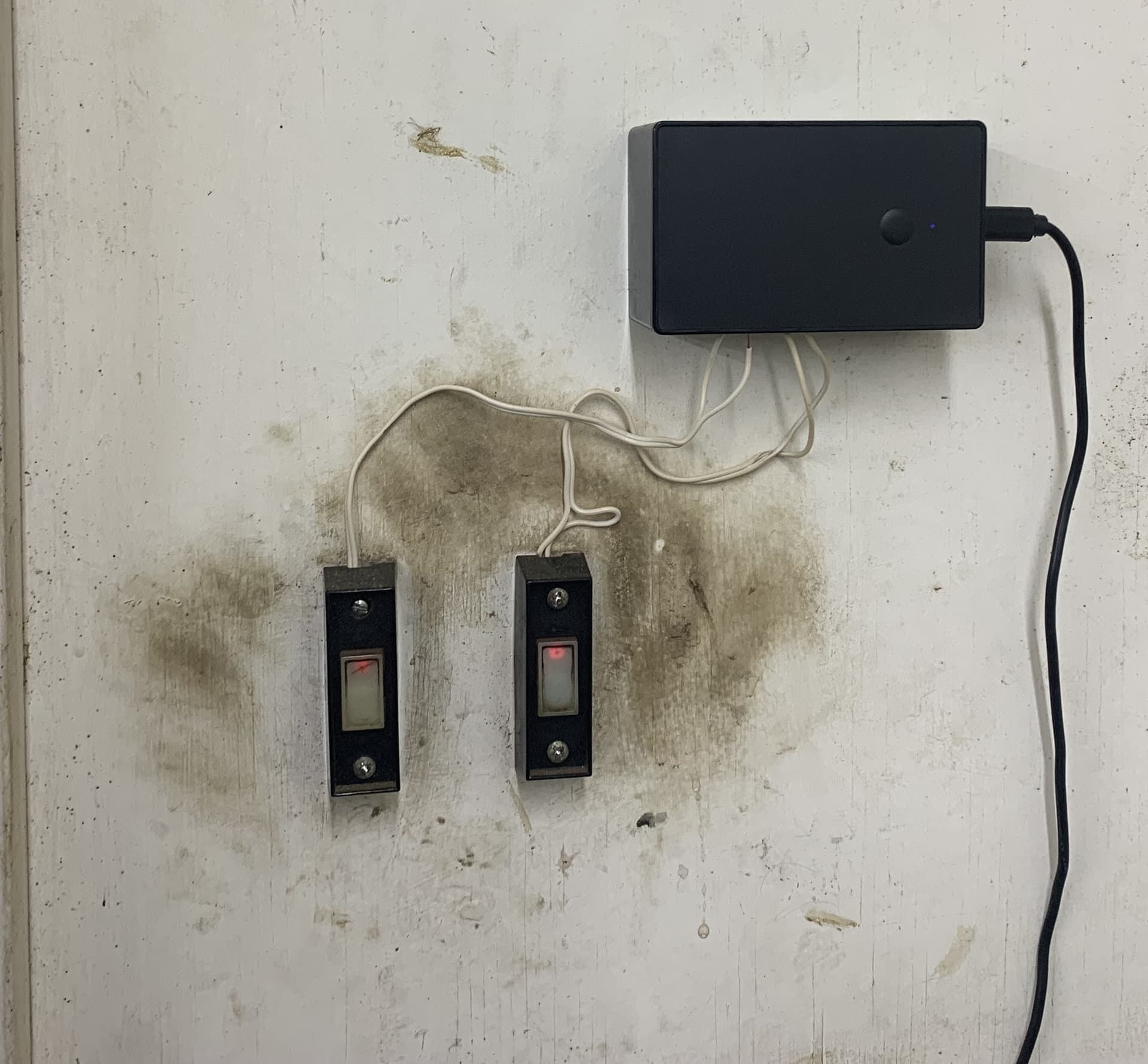
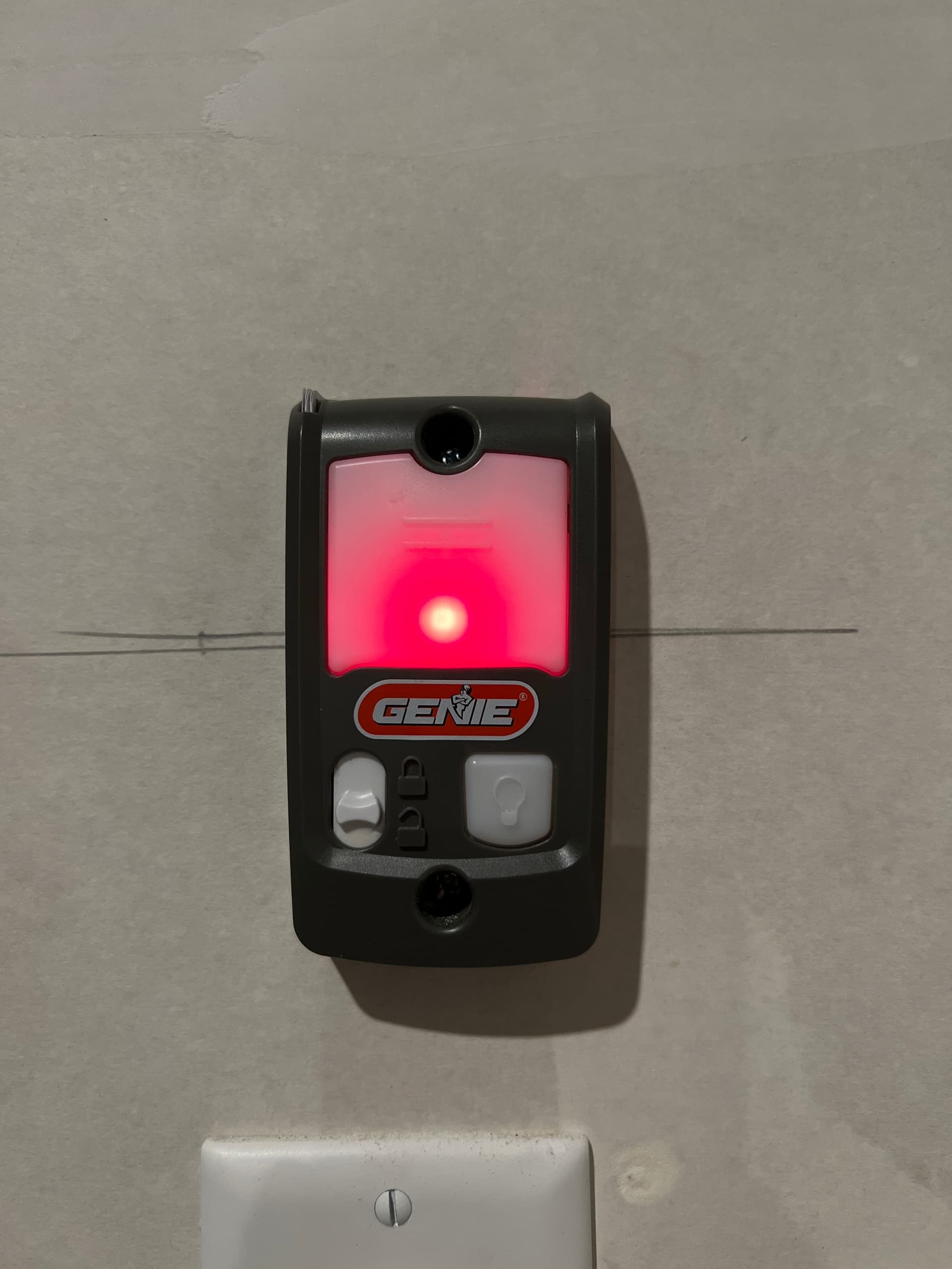
Here’s what the button and the terminals on the back looks like. Not wanting to take the CB off to see more. Don’t have time  .
.
That said, Now I’m extra curious since I can’t find on google. Any search with “garage door opener” will return myriad hits on GDO installers, dealers, and manufacturers; none of which answer the question “how does the secondary button for light work on garage door opener.”
Probably could use better search terms, but I’m not fully versed in low voltage control. Not even sure how I got the idea about a slightly different voltage being the answer.
Perhaps one of the wires send the GDO signal and the other is for the light - big button sends both signals, and small button sends the light only?
Yeah I see you already have the zen16 2nd wire pair connected to the button terminals.
Everything works?
An installation manual for the opener might be helpful to figure out how the light works.
My guess: rf like the car remotes.
1 Like
Yes! It works like a charm. Had a hard time figuring out how to place the contact sensor. Using ring contact sensors all around the house and thought I could sneak one on the side of the garage door. But the dang tension wire kept rubbing on it.
Contact sensor solution: door hinge+3M tape
For anyone else having issues or looking for a better way to use a Contact sensor for open close status of the garage door, I found this video on YouTube of someone using a door-hinge to break contact when the door rolls back to horizontal from the vertical position. Simple but effective.
Only thing I need now is a siren to alert people when opening or closing.
No need to skip around in the video he actually gets to the demo right away Alarm Contact Sensor install on garage door - YouTube
1 Like
@jtp10181 How do you control the GDO light? I have dumb buttons on the wall - 2 wire but 2 buttons, one for GD and one for light. I have wired the zen16 in parallel at the GDO - a set of wires from R1 to the same locations as the wall buttons. I can control the GDO with the zen, but have no clue as to how to control the light.
Anyone have any insight? A bunch of thread here mention GDO light control, but for the life of me, I don't know how to trigger/execute it.
AFAIK, it's not possible for the Zen to control the light in that setup (mine is the same setup). Just like I cannot control the vacation lock that's available on my wall unit.
I suspect those two features actuate wirelessly betw/ the wall unit and the opener, but I don't really know.
I don't think you can, it must work off some sort of impulse on the line. The trigger to open the door is a simple momentary full close of the switch, but the light must work off something else. My wall pad also has a remote lockout button, which again is a mystery as to how it talks to the GDO.
I've done some more testing.
The voltage is 3.87VDC between the two wires (at the wall buttons as well as the GDO). Pressing the GD button brings the voltage down to 1.87VDC (so sending 2V to the common wire?). Pressing the light button brings it to 2.05VDC (so sending 1.82V?). 0.84V if the lock switch is on.
So sending >2V = GDO Motor turns on?
< 2V = light turns on?
I don't know how I could even test this. How do I supply <2V to the common terminal to test this hypothesis, hoping the light would turn on?
If this is true and possible, I'm thinking could we connect wires to the zen's R2 with some amount of resistors to create a voltage "signal" of <2V? Relay opens for a moment, completes the circuit with <2V -> light turns on. I'm just thinking out loud here.
Possibly, if that's all it is doing, could be more more going on than what you can see with simple tools. If you really want to emulate the wall button, then you should get a spare one and take it apart, then soldier leads to the button contacts. Wire the spare wall pad to the GDO right next to the ZEN16. Then if you close those leads you added it will be the same as pressing the buttons.
You could also do that to your existing wall button if you run a 18/4 bell wire back to the ZEN16 or move it right next to the button.
No guarantees, but it should work in theory.
This is the same way you get around the Security 2.0+ wall buttons that are some sort of encrypted digital signal, so you cannot connect a ZEN16 directly to the terminals on the GDO.
Does anyone know the relationship between Genie and Overhead Garage Door? The wall console for the Series II looks IDENTICAL with just a rebranding.
The Genie Company - Wikipedia.
In 1983 the company entered the home and shop vacuum market, and in 1985 it changed its name to Genie Home Products.[2] Overhead Door Corporation purchased the company in 1994.[2]