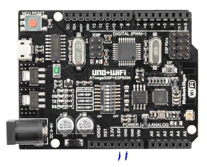
the issue is; I found a cheap card and ordered it. This one:
it has esp8266 and it is known as a UNO+Wifi Rev3 Clone.
So this is not actually a UNO.
I don't know how much ram it has but has 8MB flash.
I just received it and wrote my webserver code on it. Works fine.
Tomorrow I will receive the stepper motor and the A4988.
Hopefully I will connect them according to the diagram and my http endpoint will receive commands then turn the motor.
I don’t know what for is this loop.
MSx pins are for controlling Step Size. Motor runs quiter with smaller steps.
However for the same speed pulse rate must be higher. And for the same
distances you will need more steps.
I would recommend to use IO pins for setting up step size.
This way it will be controlled by sw.
And you are missing main power correction to the Arduino board.
I received the parts today and connected them but I have a problem.
even with no program on the board , motor starts to turn continuously.
I then disconnected the step and direction pins from the A4988.
the motor still turns when the power is supplied.
Then I realized something:
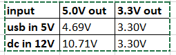
I am powering the Arduino board through DC in with 12V
the 5.0V output does not read 5, it displays 10V
is this normal ?
If I power the unit through USB, then 5.0V output shows something like 4.97V
The 3.3V output shows around 3.2V always (does not change if the input is on DC or USB)
So , if the 5.0V is producing 10V when powered with 12V , then the 10V might have damaged the A4988 because it works with 3-5V
Am I correct ?
ok. I understand you but UNO+Wifi R3 is actually an Esp8266 board.
When I check the nodemcu-esp8266 board , I see that it is very small compared to the Uno+wifi and I am not sure if provides all the output for this setup.
Besides, it only has USB power input. Which means then I will have to use 2 seperate power supply (one for the motor (12V) and one for the board (5V))
ESP8266 is a CPU.
Uno is a Board which has ESP8266 as a Part plus whatever else including on-board voltage regulator. ESP8266 and ESP32 have more than enough IOs for yours application.
Yes, in case for ESP8266/ESP32 you will need 12-to-5V downconverter.
Please make sure it is switched (not linear) downconverter.
You most likely wired it to the wrong pins. The 5V out pin is the same as the supply for the atmega so if that were 10V it would have fried your uno too.
looks correct but the 5V pin comes out of the same regulator as for the board itself so there might be a short somewhere. I'm surprised the board itself is ok unless there is a protection diode somewhere.
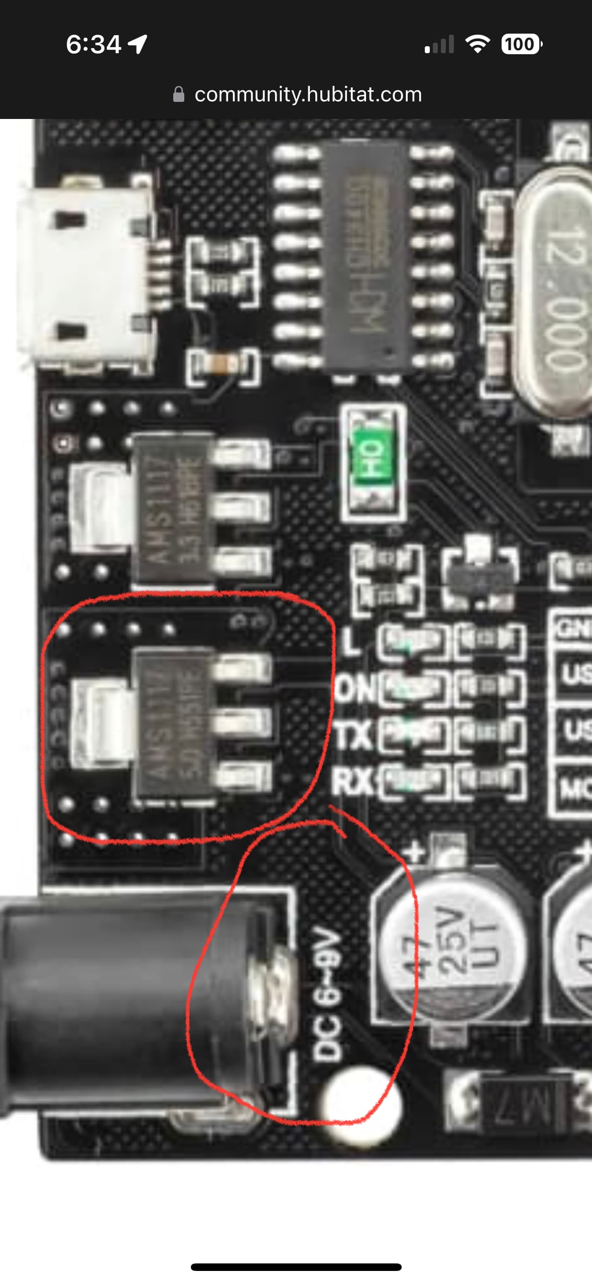
That UNO-WiFi board appears to only be rated to handle 6-9VDC on its barrel power supply input connector. Applying 12VDC probably fried the 5VDC regulator chip.
but the specs says " * Power jack, 7-12V power input."
here:
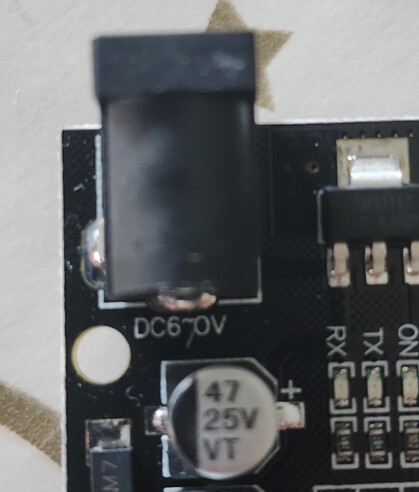
So I never checked on the board. Well, I'm not sure if it would matter (have I looked) because as you see in the photo above mine doesn't even say 6-9 (says 6-0)
I guess it is a bad clone.
If this exact board is what the OP has then the AMS1117 in the picture can handle 12V. It's more likely OP got a faulty board which looks like a non original uno wifi.