WIFI 104 - 433 - Swimming pool led lights - help

I will try to keep this short...

I am wiring some swimming pool lights (under water), my parent got some WIfi 104 controlled constant current LED's RGBW.

I wanted to wire them into a shelly or a Fibaro controller but I do not think I can do to the fact that they are constant current.

The only solution I can think of (well simple way) is to wire across some button on a spare remote control that works with it.

Can I solder on to a capacitive button and use a relay to close?

My aim is to use habitat to turn the lights on when the pool cover is removed, which I can do by using a volt free contact on the cover controller.

thanks for any help.

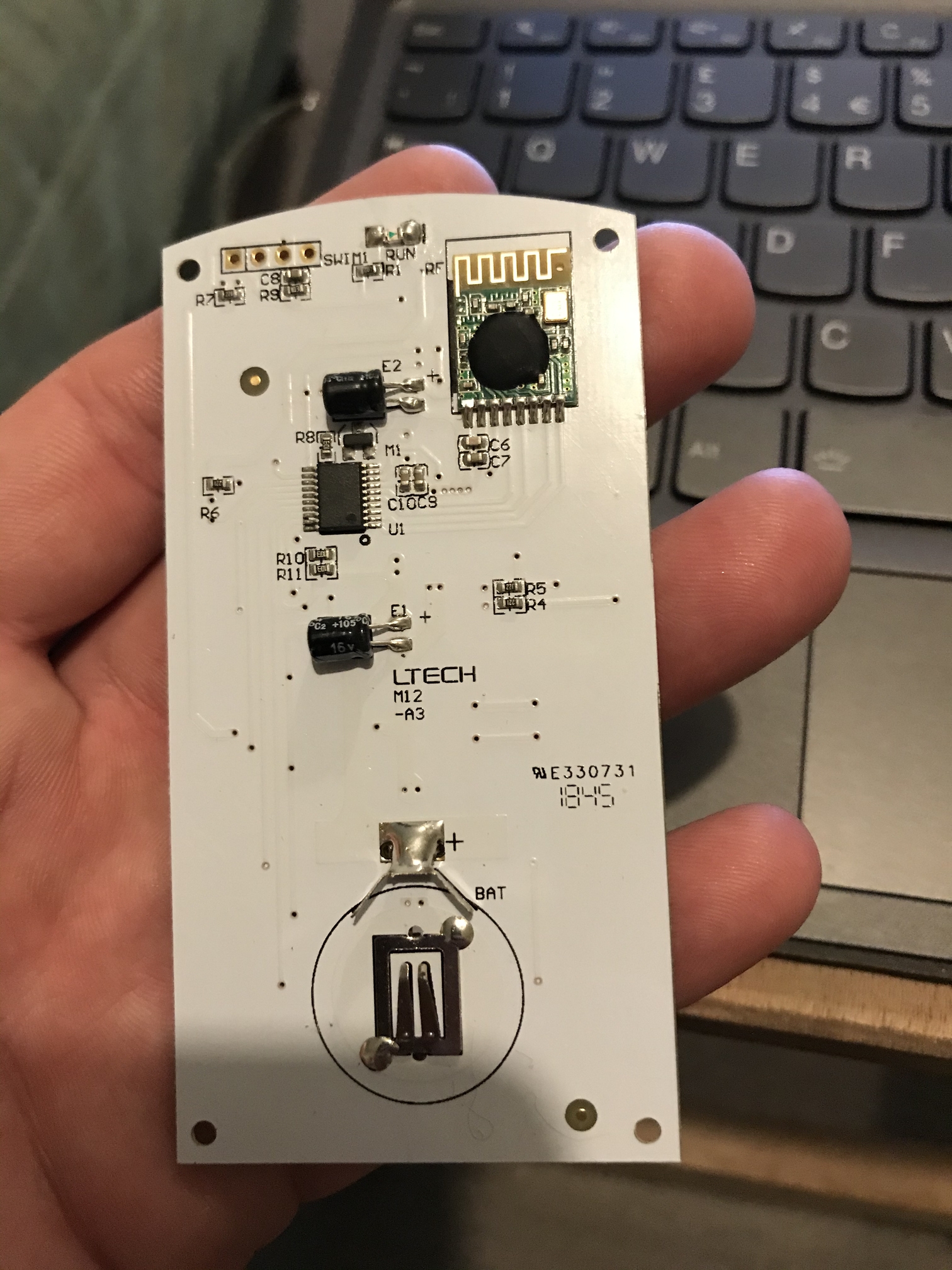
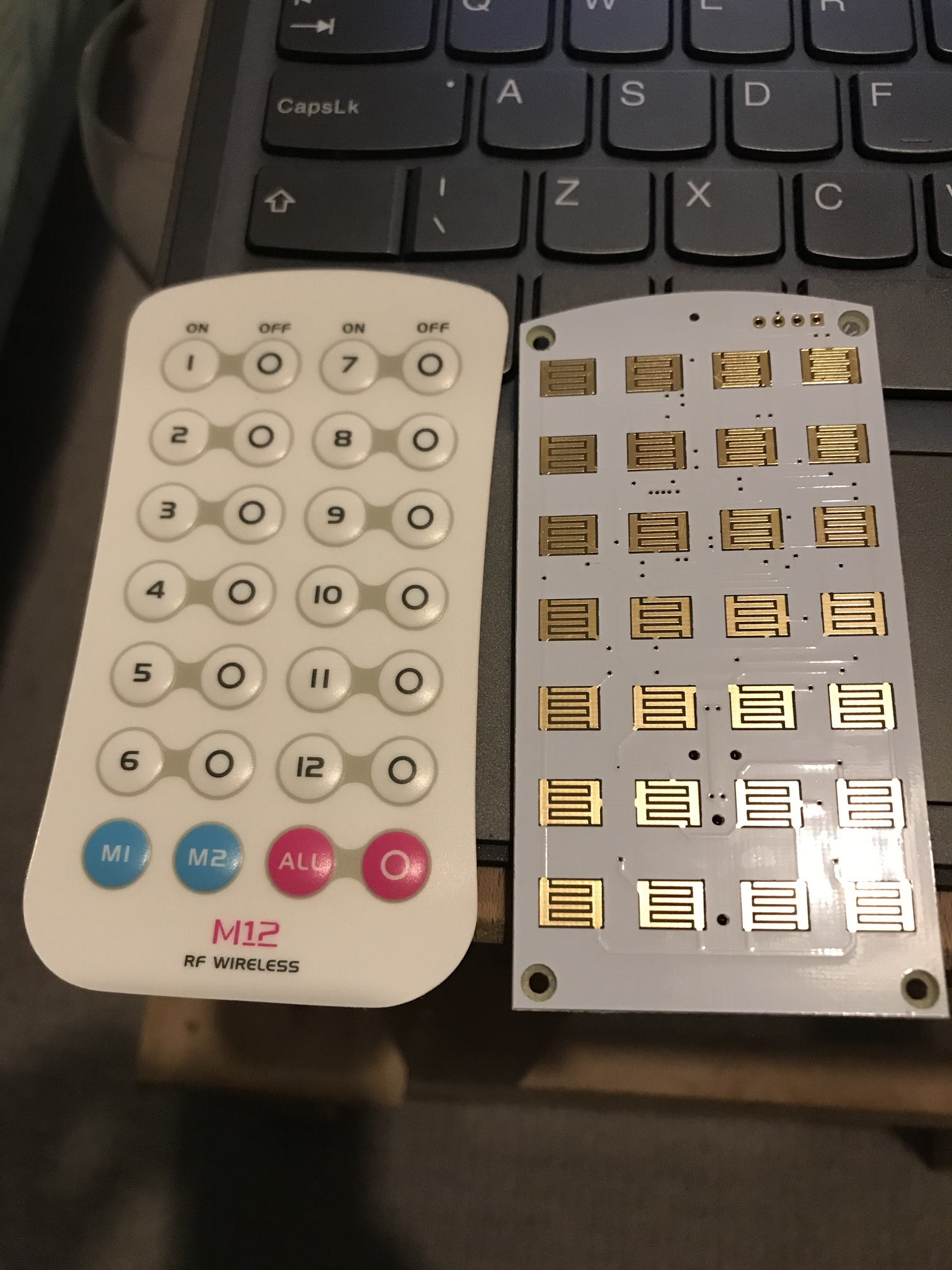
Typically not easily, as any extended wires will affect the capacitance of the terminals your connecting too, however those little gold interlocking finger pads, look to be resistive button pads, to which you should have more success.
Confirm this by checking if the under side of the buttons have a small black carbon impregnated pad that β€œshorts” the gold fingers when pressed down.

the pad does have black pads so hopefully it will work. I will give it a go tomorrow.

Thanks

1 Like

I agree with njanda regarding the resistive shunted pads. I suspect long wires on these pads (even if resistive) will be problematic.

I don't know how many circuits of RGBW's you have but an alternative is:

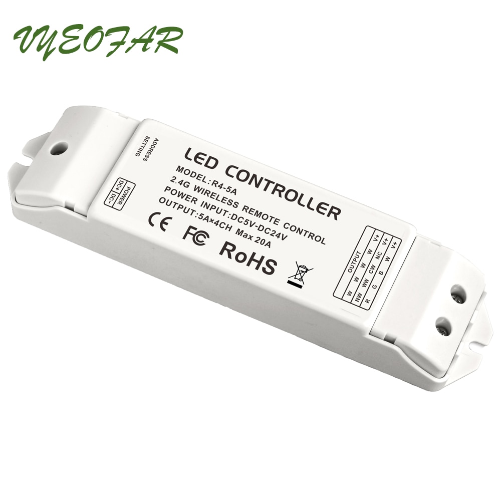
Change your LED controller for 4 PWM to Constant current drivers. Meanwell makes some nice ones and not too costly. You can then operate them from a single fibaro RGBW controller.

You would have to know:

  1. what it the max current your leds will take.

  2. How many LEDs are in series and what voltage do they need to reach max current.

See here and here

The constant current drivers are really easy, its just they aren't used for the 12V eBay strip lights. All commercial LEDs use constant current.

If you want to go this way I can guide you.

John

1 Like

It looks like the controller is RF, if it's 433mhz maybe a broadlink pro or sonoff RF bridge would be an option also.

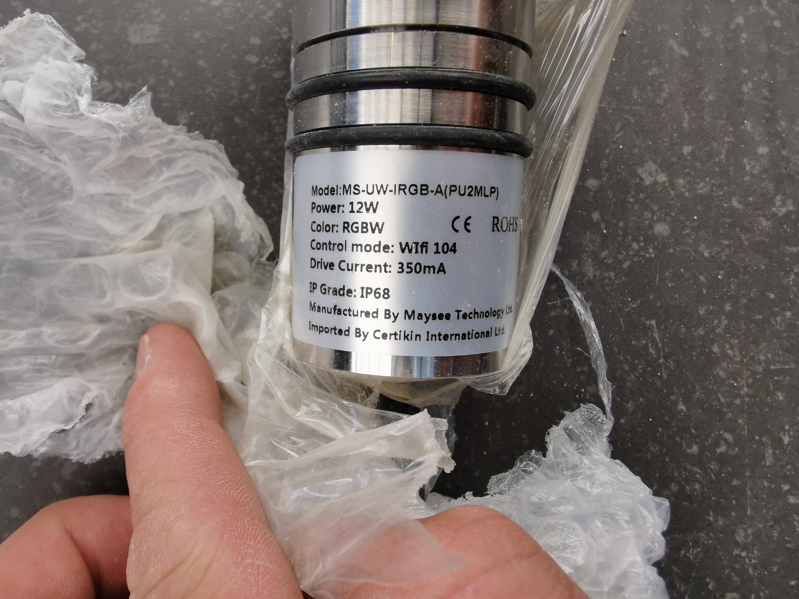
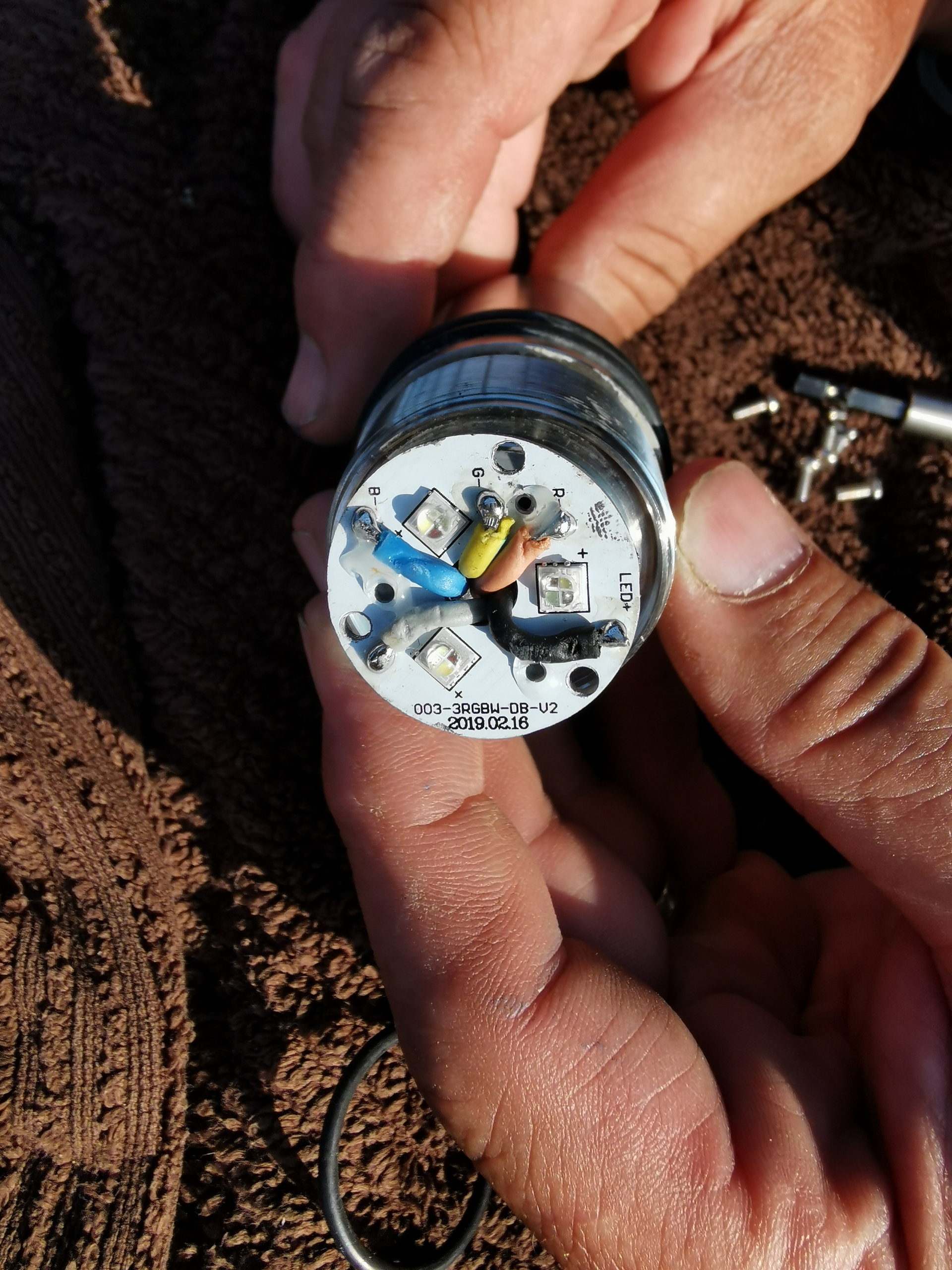
this is the name plate, they are currently running on one constant current driver each. I made the mistake of connecting them to a shelly RGBW module and damaging them all - which didn't do down well!!

I will research PWM to constant.

ouch

1 Like

it was! Β£400 for 4 new lights at cost! I will not make that mistake again.

The Shelly RGBW device only uses DC as input/output and its max is 24V -- standard operating voltage is either 12 or 24V DC. AC will kill everything.

The part number on the device in your photo suggests the "driver" is built in. So my suggestion will not work.

The Maysee website suggests there are multiple versions with different control schemes.

Perhaps if you showed what you have someone might be able to suggest some direction.

Question: Do you have the devices working with the equipment you have?

BTW I know this is too late for your first round of testing but you should get some 100 ohm resistors to put in series when first testing an unknown configuration.

John

The current setup is a 24vdc power supply to WiFi 104 controller which is connected to a Ltech driver below.

The led on the light looks like...

My ultimate goal would be to have total control via hubitat.

This topic was automatically closed 365 days after the last reply. New replies are no longer allowed.