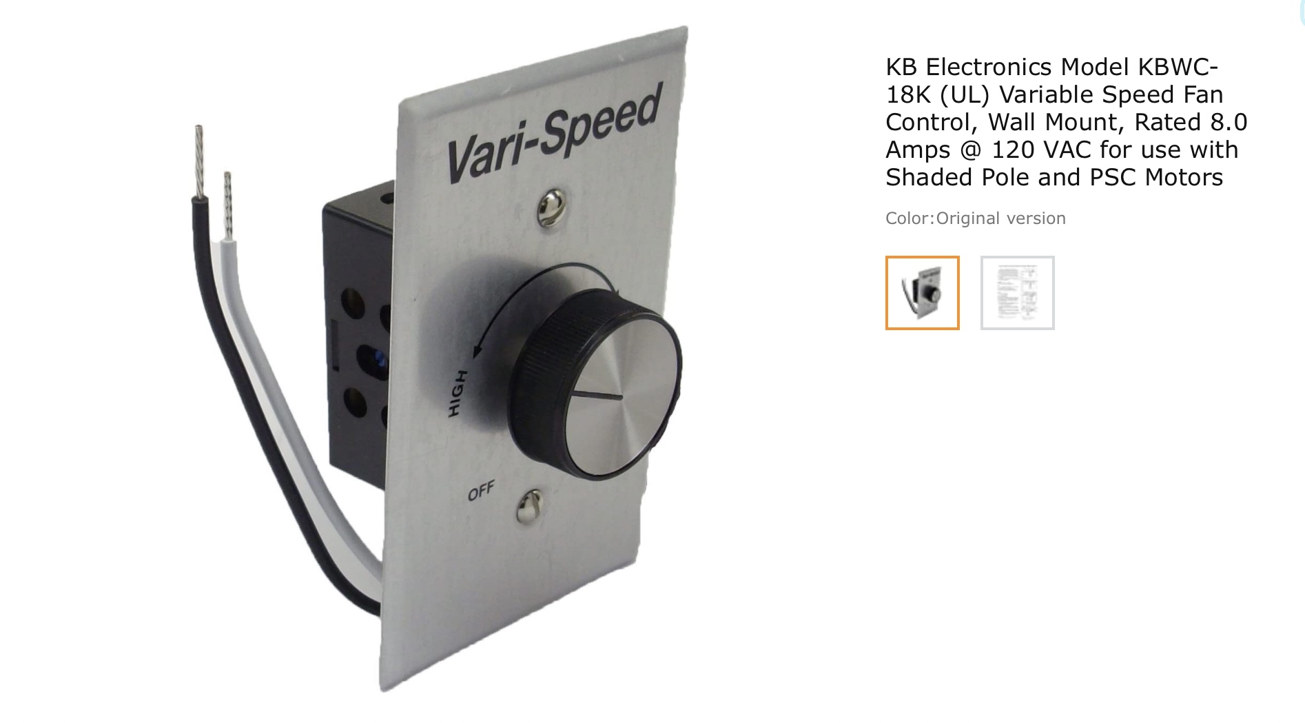
This is wired in series with the black wire at the fan. The speed is infinitely variable.
I have yet to find a Zigbee or Z-Wave speed controller that can handle 8 amps (960 watts).
Is there something I can attach to the front of the control that can rotate 270 degrees and compatible with HE?
How often do you change the speed? You could use a dry contact relay between this controller and the fan to control when it’s on. In other words you set your existing control to the desired speed and leave it on and the relay controls the output to the fan. The Zooz Zen16 should work but I would confirm with Zooz support to ensure the ratings will work with the relay.
The speed of the fan is usually determined by my wife’s cooking skills and/or the ambient temperature.. Rarely is it full speed. I could use a step type device that would allow low, medium, and high.
There are only 2 wires to the control, so anything that needs a neutral will not work.
My 1969 built home has no neutrals. Not even in the attic. I agree I am not going to find a Zigbee or Z-Wave control. Perhaps a servo mounted on the knob would work.
I ibstalled the fan over 35 years ago (naturally in the heat of summer).
A typical light bulb circuit at my house has a black wire and a white wire coming out of the fusebox. From there it goes to a switch that breaks the black wire. The black wire from the switch and the white wire go to the bulb.
There are a few upstairs rooms in the house with only 2 wire outlets.
I tapped into the black and white wire in the attic. Black goes to the speed control and white continues to the motor. The black wire coming from the control goes to the motor.
I would have wired it differently, but when there are no neutrals anywhere in the house, there isn’t much that can be done.
Assuming you live in North America… it sure sounds like those white wires are neutrals to me. Unless every single device in your home operates at 240VAC, your have neutral wires in your house. It is the only way for a 120VAC circuit to function.
Now, it is completely possible that you have no neutral wires inside your in-wall switch electrical boxes. However, there will be a neutral at the light fixture still.
Every 120VAC outlet has a neutral wire as well, even if there is no ground wire.
Any chance you have neutral and ground confused? There has to be a neutral at every 120V AC powered device (lights, fans, etc) to provide a return path for the current.
Black, white and bare copper. I gutted the basement years ago and traced the circuits back to the panel. Opened the panel carefully and only have three 220 volt large black wires breaking into 2 110 volt branches. The house has 100 amp service with fuses.
I don’t know if it is to current code, but it must have passed inspection in 1969.
This isn’t a pressing need. The fan is begging to be automated. It is the only device that is not. The fan is old. I bought it in the early ‘80s (quality Emerson direct drive capacitor start motor) that my dad received at cost when he was an exec there. Got a nice Fisher receiver and speakers at cost also.
Thinking about the fan, I would be happy with 3 or 4 speeds. Infinitely variable is not necessary.
But each circuit only has a black and white wire coming out of the panel.
Years ago I was in the attic checking for neutrals when I began with ST. Had drywall replaced in a few rooms around the same time. Was able to see the Romex right to the back of the box. Everything was 12/2 with ground going into the outlet boxes. For the switches, the Romex is cut open. The black wire is cut and the ends go to the screw terminals on the switch. The white wire and bare copper ground wires continue to the bulb. It is a basic switch circuit.
Been like this since 1969, and we have lived here since 1982 with no issues.
Yes, this is for a 120VAC circuit. The black is typically HOT from the circuit breaker (or fuse if your panel is that old ). The bare copper wire is Ground. The white wire is Neutral.
Voltage is bit tricky to visualize because you can't really have a single wire measured at some voltage. It has to be measured as the difference in potential between two things. If you measure 220 volts, it must be the voltage potential between the two hot wires. Either wire measured against the third (neutral) or the panel ground will be 120 volts. This is true in your boxes as well. The hot wire will measure 120 volts with respect to the neutral or ground, and the potential between the ground and neutral should be zero volts.
That video is pretty good. I've also found that a basic homeowner electrical book can be a great resource for helping identify various circuit wiring layouts when they don't make sense (at least to me) or use white as a hot conductor, etc.