So I love playing around and tinker. I started playing around with arduinos and thanks to @ogiewon, I rediscovered my electronics hobby (no formal electronics nor coding so be nice  and with his aid back on ST days I started deploying diy sensors all around. Later on my wifey started complaining of how ugly and out of place the sensors looked (I was prototyping my arduinos on plastic battery boxes or empty pill bottles lol). So she got me thinking on how to hide all my diy IOT sensors that they could mix into the rooms and be the most inconspicuous I could. My first idea was to buy cheap chinese night lamps and with some trial and error I was able to tap into the circuits and make them turn on/off with the GPIO of the arduinos that deliver 3v while high. Then I came across with some with night lights with PIR's and adapter those as well. As of now I have deployed about 15 devices all over the house with the intention of maximizing all the telemetry I could, to take logic decisions on all the automations. The sheer amount of arduinos made administering all those a very difficult task, with stanything (thanks for your great project Daniel) as getting status of the actual arduino or remotely restarting the device would be somewhat cumbersome. Then I stumbled at Markus project with his take on a Tasmota derivative, modified to talk http with a set of solid drivers. This has been a game changer in my use case scenario, as not only I am able to interact with Hubitat, but also have the ability to manage the arduinis with MQTT!!! Thank you Markus, for all your great drivers and contributions, 100% of my arduinos are now converted to Tasmota thanks to his project T4HE.
I wanted to share my newest contraption made with the Tasmota version from Markus firmware, with some script monkey action and copy pasta I was able to compile the tasmota sensors and display drivers into one image.
This is an early prototype:
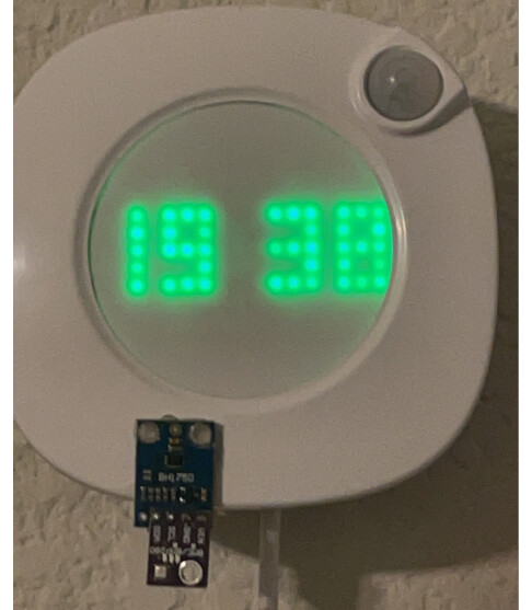

First attempt with a oled display with a $1 led battery night light:

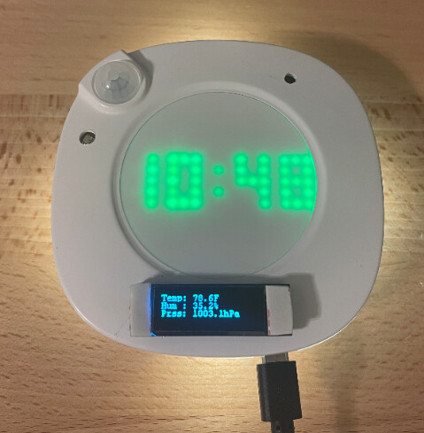
Fast forward to today's proto, the idea is to be able to have a quick glimpse without having to query thru an app:
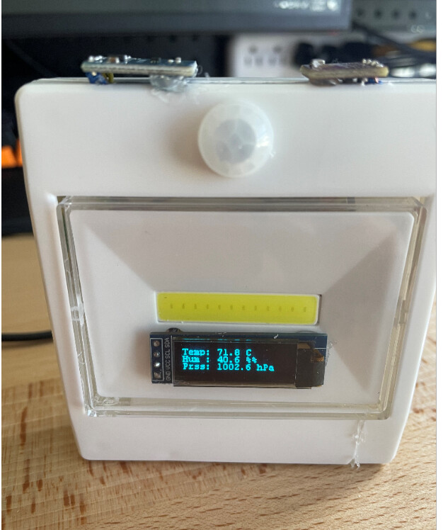
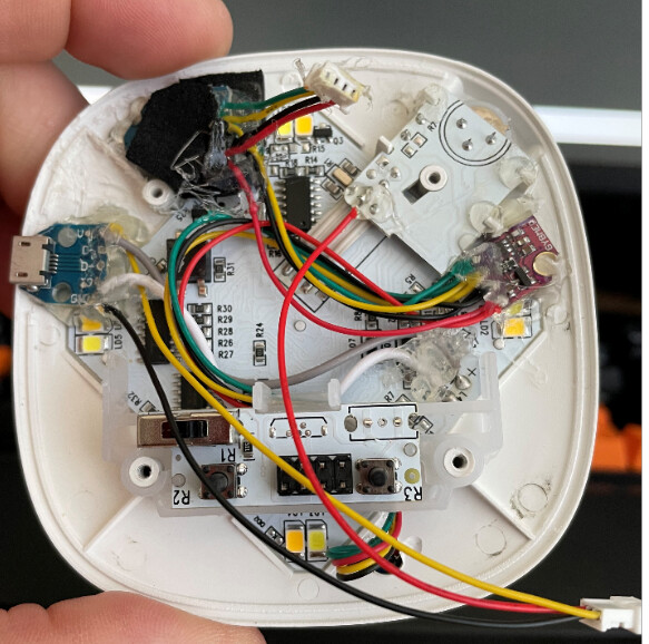
Some of the innards:
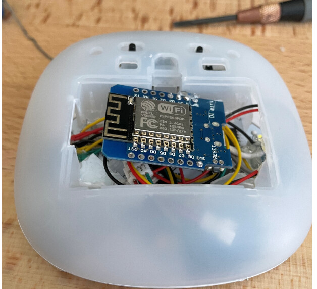
How it fit:
Tasmota:
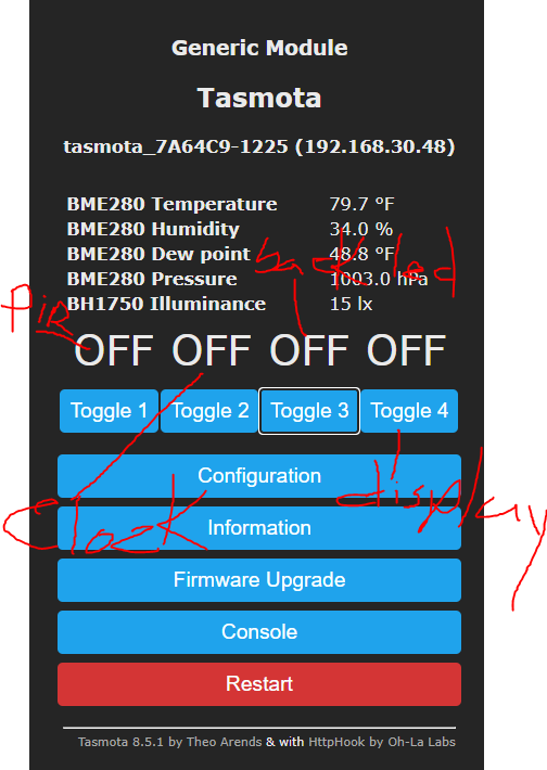
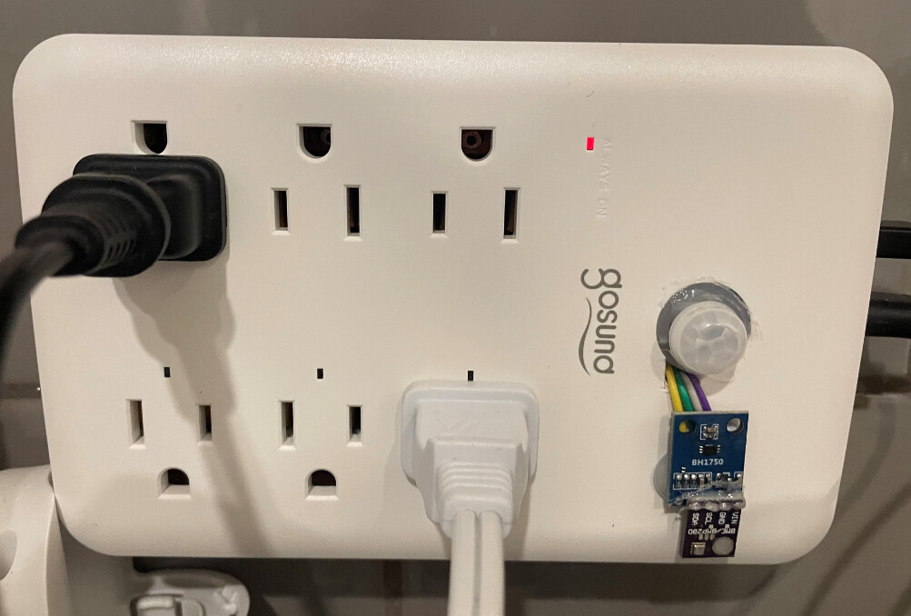
So I used a BH1750 for illuminance, BME280 for hum/temp/pressure, a SSD1306 display. Tapped into the already built in PIR, removed some resistor from the original circuit design and now I can control the LED Clock and back LED's individually.
For those interested here is the template used:
{"NAME":"Generic","GPIO":[6,0,5,0,0,0,0,0,22,23,9,0,21],"FLAG":0,"BASE":18}
Tasmota Rules, such a way it doesnt even need external intervention to be used as a night light or to display text:
{"Rule1":"ON","Once":"OFF","StopOnError":"OFF","Length":483,"Free":28,"Rules":"ON Power1#State=1 DO power2 1 endon ON Power1#State=0 DO backlog power2 0; power3 0 endon ON tele-BH1750#Illuminance==0 DO rule2 1 endon ON tele-BH1750#Illuminance>5 DO rule2 0 endon on tele-BME280#Temperature do DisplayText [s1p21x0y0]Temp: %value%F endon on tele-BME280#Humidity do DisplayText [s1p21x0y10]Hum : %value%% endon on tele-BME280#Pressure do DisplayText [s1p21x0y20]Prss: %value%hPa endon ON Power1#State=1 DO power4 1 endon ON Power1#State=0 DO backlog power4 0 endon"}
{"Rule2":"OFF","Once":"OFF","StopOnError":"OFF","Length":35,"Free":476,"Rules":"ON Power1#State=1 DO power3 1 endon"}
Hope it inspire someone, let me know if you would like to know any aspect of it and gladly will share.