Wondering if anyone in the UK has automated their TV bed and what they used/how they did it. I've been meaning to have a look at mine (bought from TV Bedstore) for a while as it would good to use it as a morning wakeup.
The bed lift is currently operated by a nasty, cheap looking remote only. I've opened up the controls in the bed base and there is a "dead man" two way retractable switch for up and down (press and hold - movement stops on release) If held the motor cuts out on its limits automatically at the top/bottom. My preference is to hook up to this switch for simplicity. My thoughts are:
1 - Fibaro Double Smart module (or any other module with a dry contact) connecting the common of the existing switch to the input of the module and the two outputs of the module to the up/down contacts on the existing switch. That would work fine but I would have to set up a rule to auto switch off after motor travel time plus a few seconds - otherwise the module would lock out operation from elsewhere (the remote)
2 - Fibaro Smart Implant. The TV bed controls are powered by a 21V DC switch mode power supply. The smart implant may be better than 1 above as the driver has an option for "auto off" on the two outputs - so the cut out timer could be set directly in the device preferences without the need for any rules.
3 - Qubino Flush Shutter DC. This might work but the output would be connected to the existing switch, rather than the motor itself. First I'd need to check that the common of the existing switch is connected to the +21V DC of the PSU as the outputs in the module are switched internally to the positive supply voltage (12-24V DC) I'm also not sure that it would successfully calibrate and see the limits of the motor.
Interested whether anyone has completed the automation or any observations. Thanks
So I got this all working the other day using the Fibaro Smart Implant in the end:
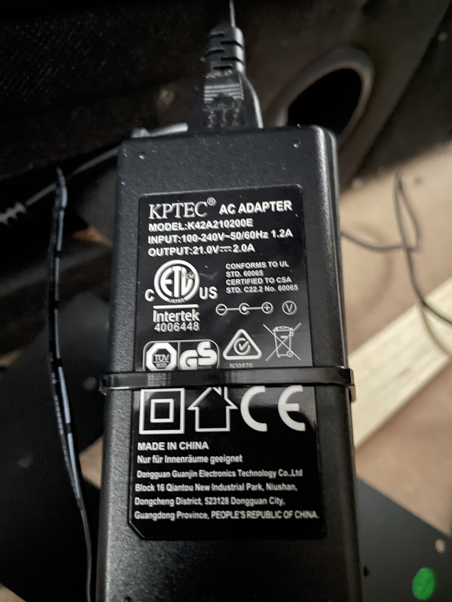
1 - The bed controls were supplied with a 21V DC PSU. I used this to power the Smart Implant (which accepts 9-30V DC)
2 - The two outputs of the implant were spliced in to the wiring supplying the existing dead man switch at the controls. As the switch needs to be held for continuous movement in either direction, I measured the time taken for a raise and a lower operation. The implant preferences allow an "auto off" time to be set on the outputs. I set those auto off times to raise time plus two seconds and lower time plus two seconds. Adding the auto switch off prevents the implant switch from locking off the motor in one position (preventing use from the switch or the remote).
3 - In the preferences - the two inputs of the Smart Implant were isolated from the outputs. They were then connected to a 2 way retractive centre off switch located at the bed head to add manual control. Two rules were set up in HE to link the momentary switch input to the relevant output - raise and lower.
The TV powers on automatically when the bed is raised. So now I can raise and lower the TV using the new switch, Alexa command and my dashboard as well as add it to a good morning routine. All that's left is to add a virtual switch to HE and add a rule to change the status of that switch so that I can have a dash icon showing whether the TV is up or down. Happy days 
pics would be interesting =)
On it - will post back shortly
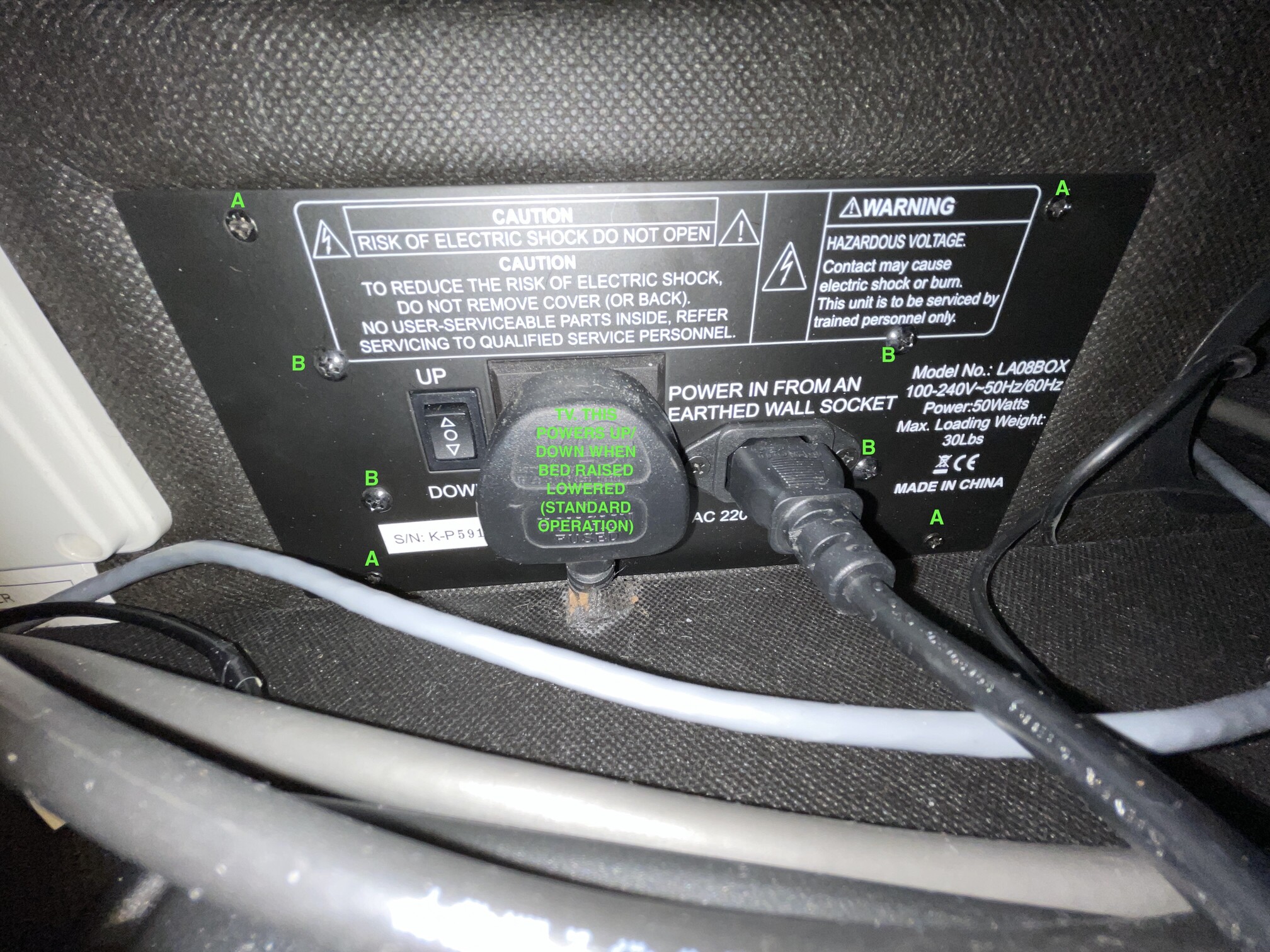
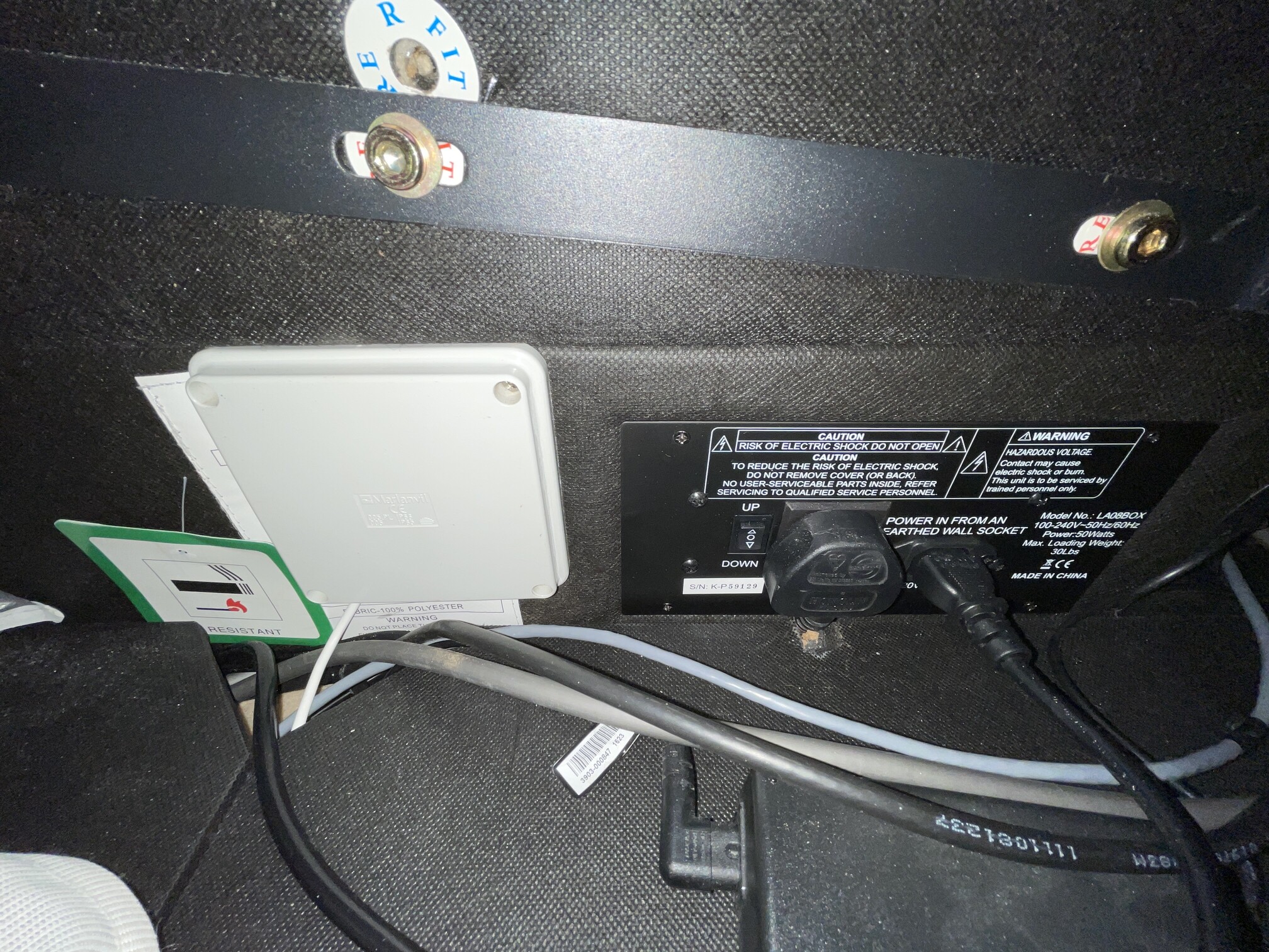
1 - Powered down - removing input cable and plug for TV
2 - Remove the four screws marked A. These hold the entire assembly into the lower bed head. Because of the angle of the cables behind I couldn't withdraw it at this point.
3 - Remove the four screws marked B. These fasten the metal cover plate to the controls behind. Pop this to one side.
4 - The controls can now be pulled forward through the opening in the bed.
5 - The 21V PSU is cable tied to the back of the controls. I spliced into the cable behind and connected a length of cable to this to supply the Fibaro Smart Implant
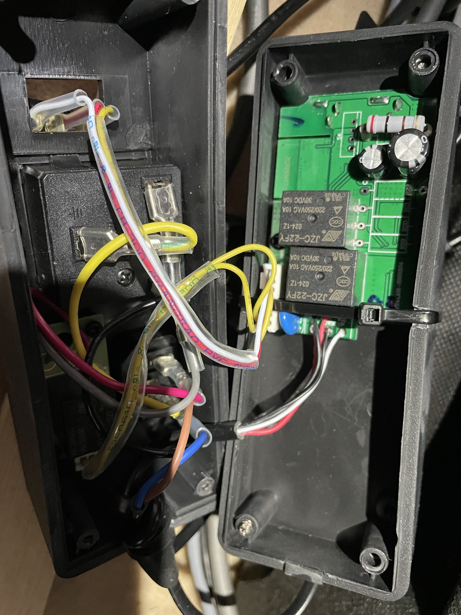
6 - The case is held together with 4 screws. Picture below shows the case opened. You can see at the top where I've popped the dead man switch out and the three wires connecting it to the PCB.
7 - I put a small hole in the back of the case and passed a length of low voltage cable into it - I used 6 core alarm cable as I had it (I'm a security installer)
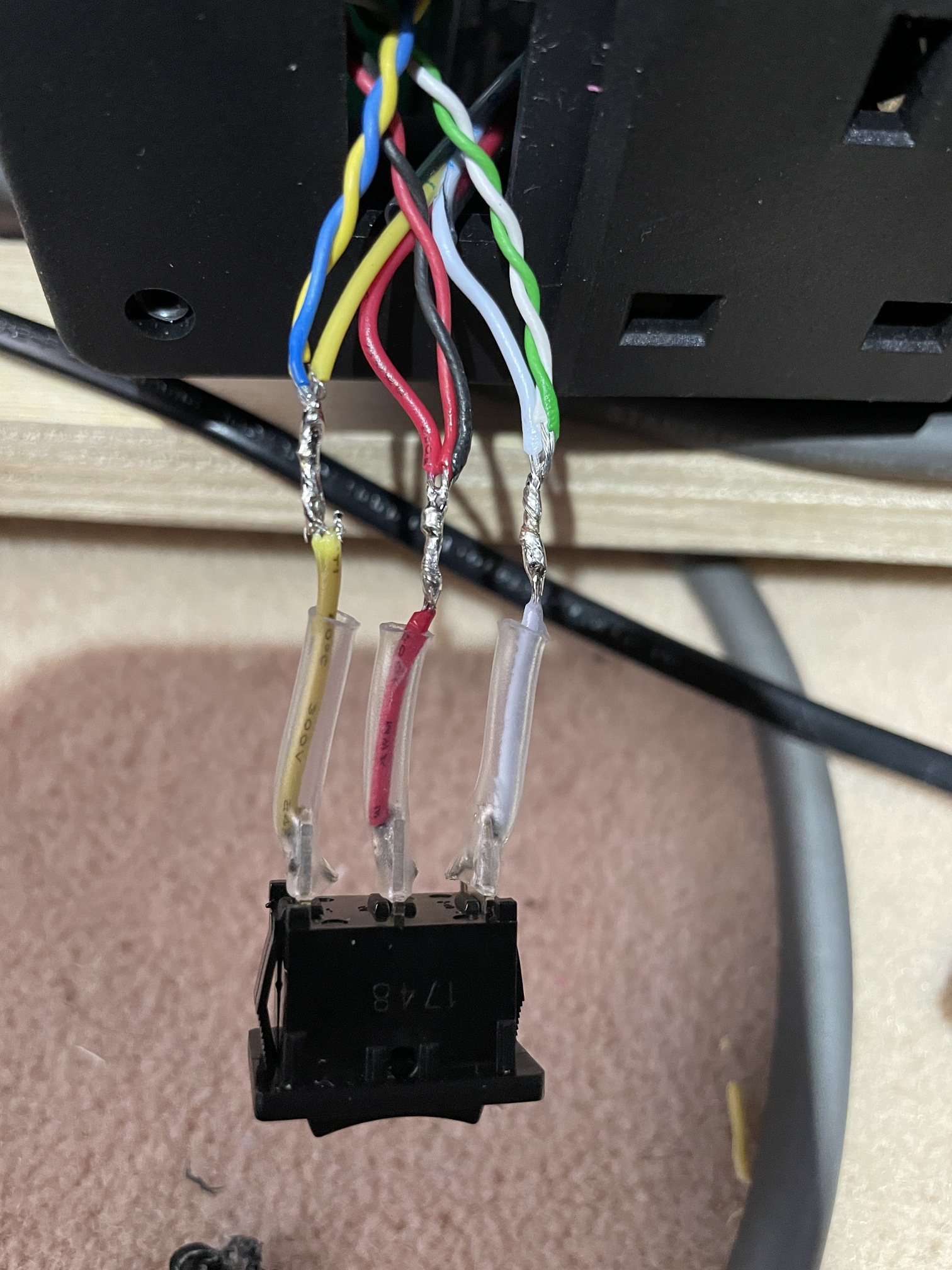
8 - I bared back the insulation on the three wires going to the dead man switch and soldered on my cables. I doubled them up into pairs (not necessary). I could have soldered directly to the switch contacts but chose not to, as it's possible to melt the switch contacts into the plastic switch if the soldering iron is too hot - not worth the risk.
9 - I drilled a hole in the base of the bed adjacent to the controls and ran three cables through the hole (the cable to the PSU, the cable that I soldered to the switch and another that would be routed to a manual switch at the bed head)
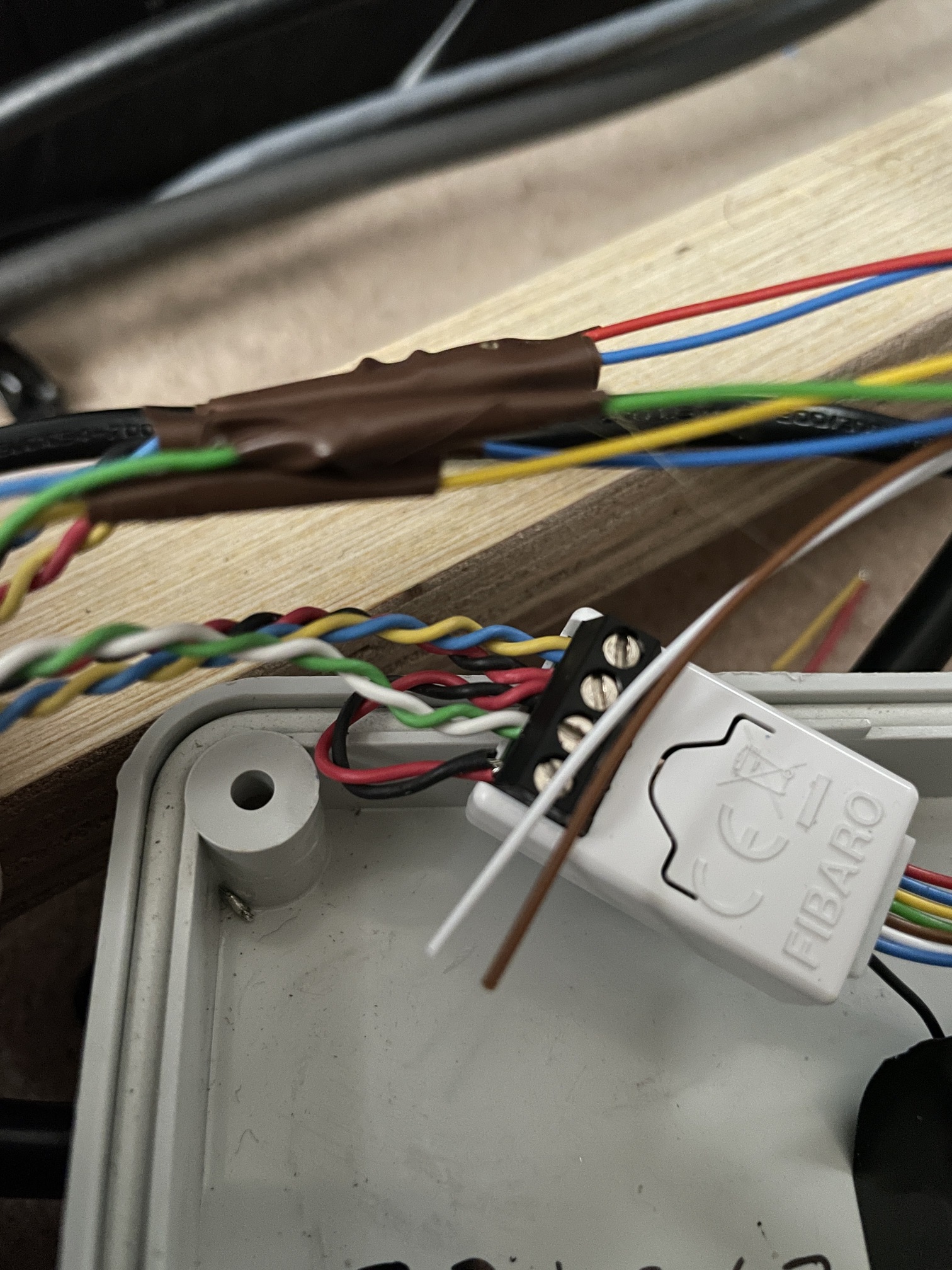
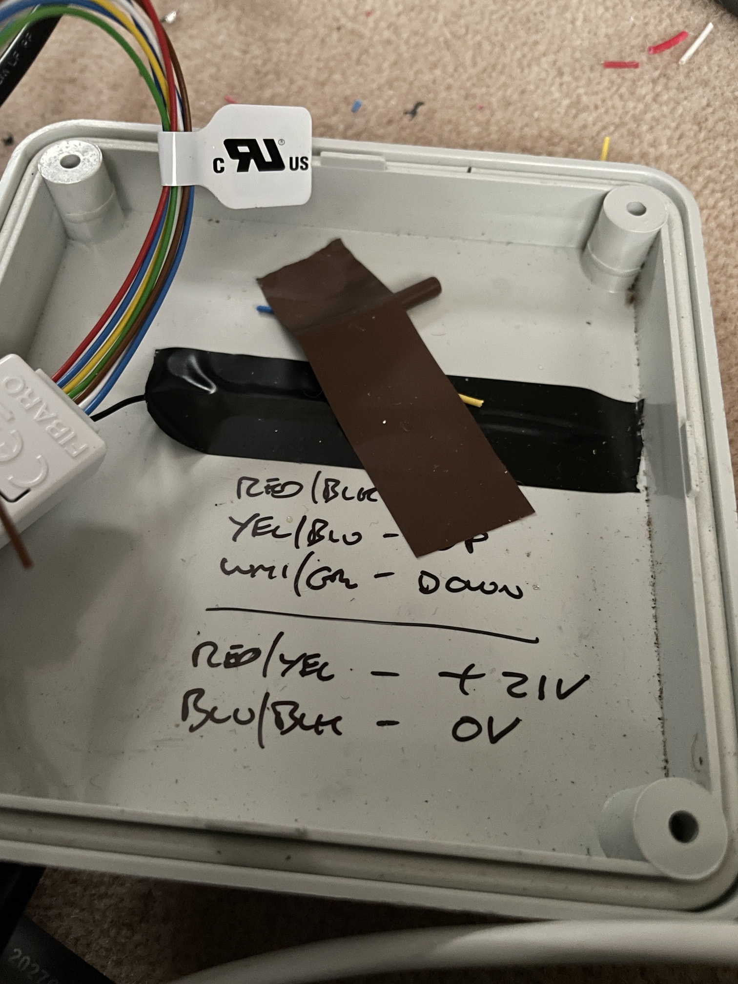
10 - Cables connected to the smart implant - outputs 1 & 2 for raise/lower, inputs 1, 2 and ground to bed head switch. I've used the lid of an external enclosure here but a standard 1 gang 13mm surface backbox and blank lid would've been neater (couldn't be bothered driving to Screwfix!)
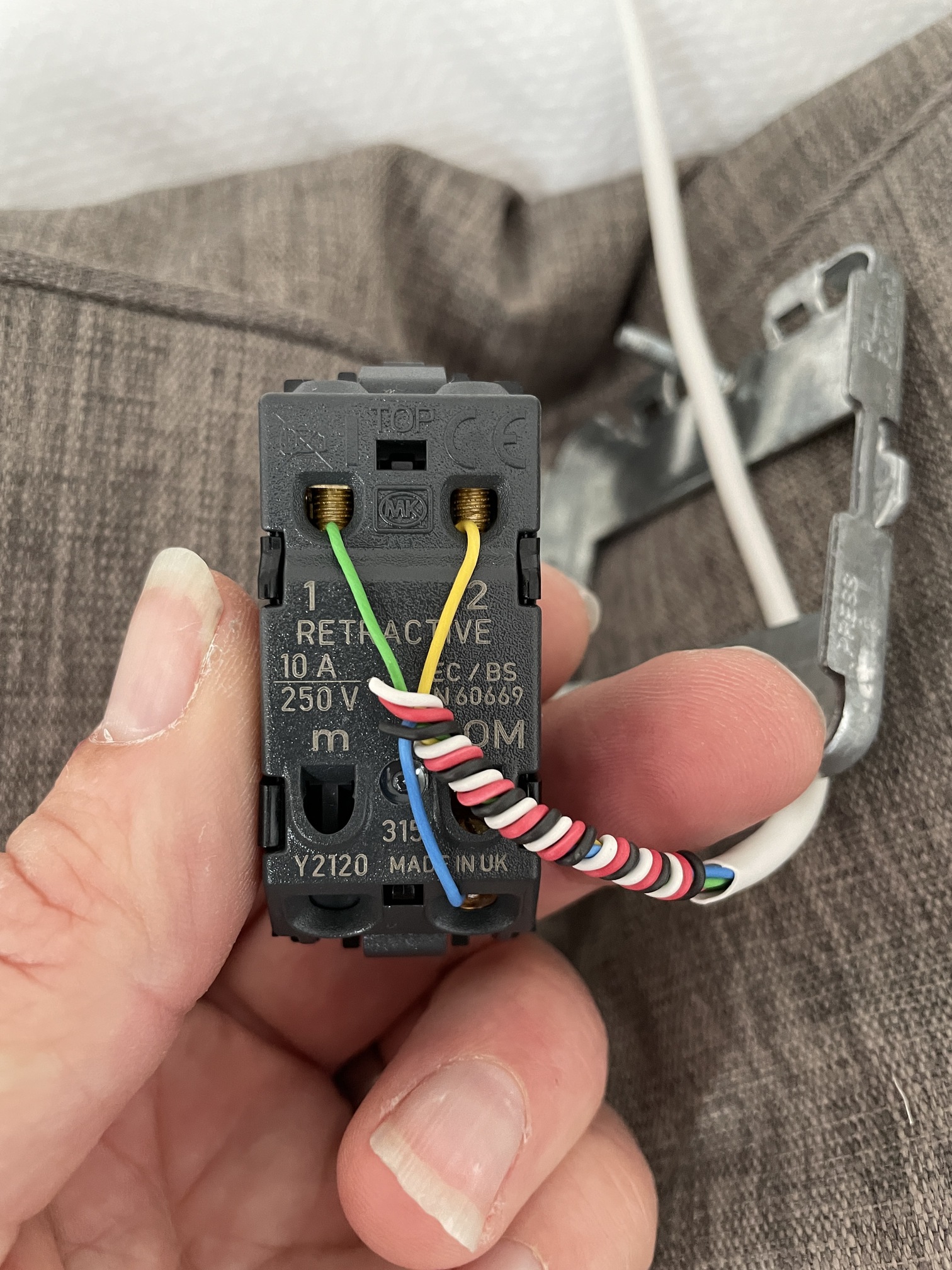
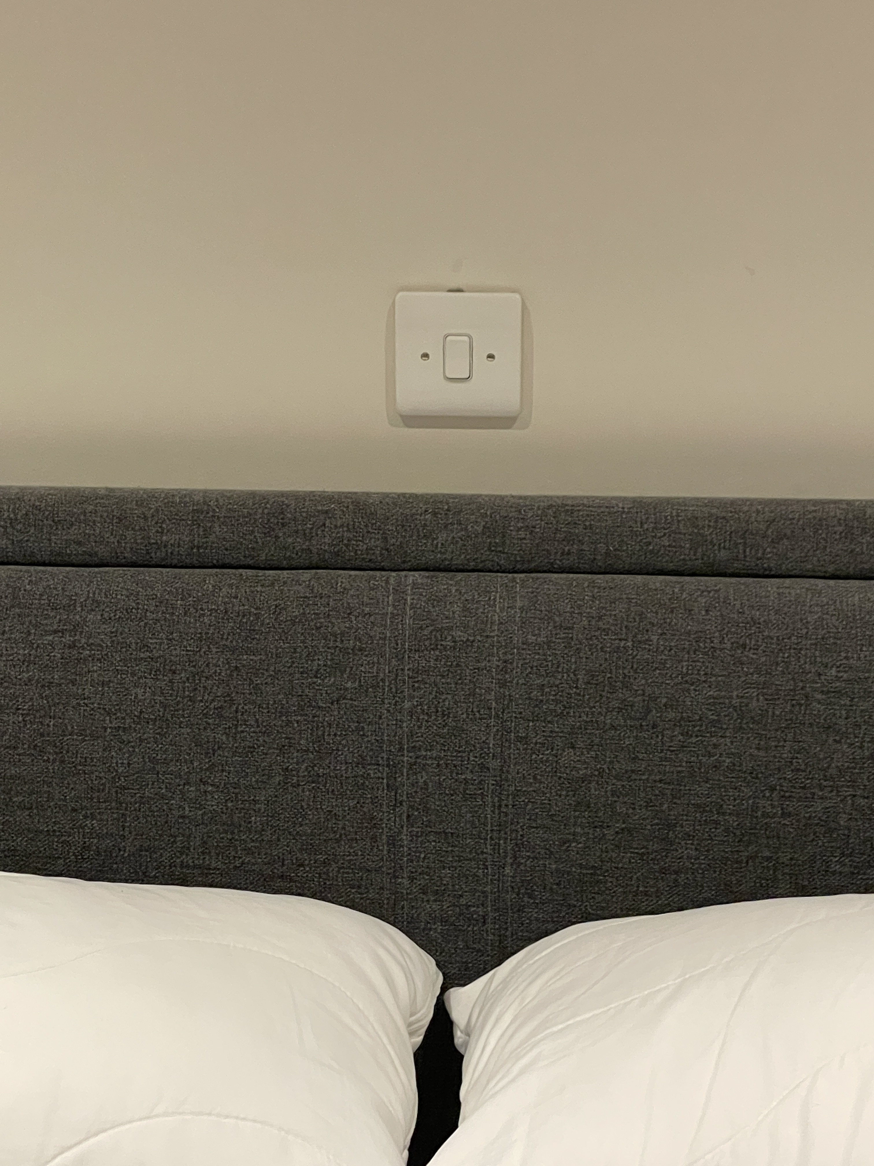
11 - The cable for the manual switch was connected to an MK grid switch (I've used these throughout for my dimmers)
And that's it completed
2 Likes