I managed to refine a few items related to control:
-
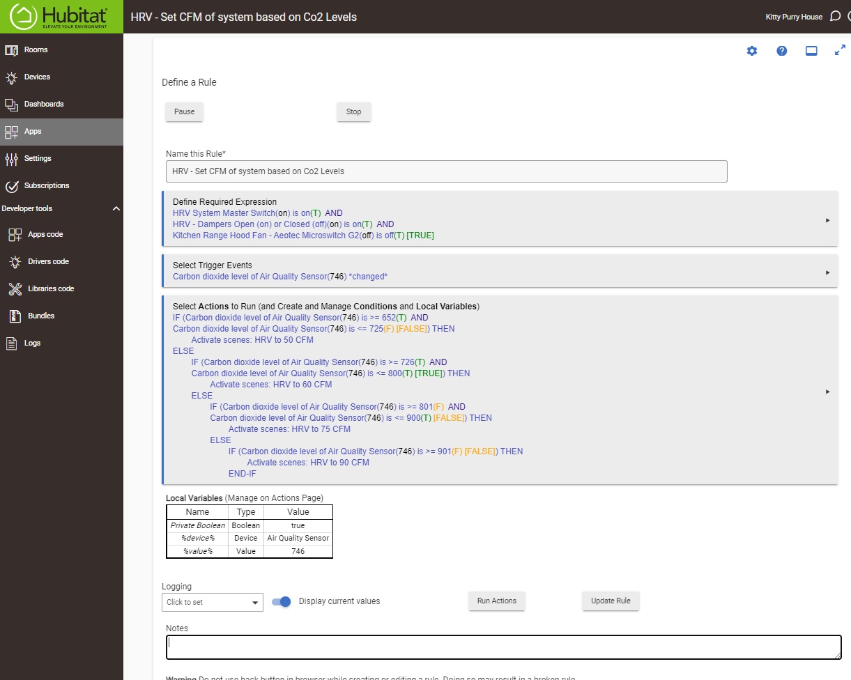
Co2 levels in the house now actively control the HRV's air flow.
-
Heating of the air into the living space is now actively modulated based on a combination of the HRV CFM air flow setting, and the difference between incoming air temp vs target air temp. This is pretty cool...the wattage output to the inline heaters is recalculated and adjusted every time the incoming fresh air temperature changes, or CFM changes.
If the HRV is running at 50 CFM, and air is coming in at 58 F (cuz it's 8 F outside!) then we can figure out how many btu/watts are required to heat that air. The formula for BTUs required is 50 CFM x 1.08 x Temp delta. So if we want 50 CFM of air to be 68 F hitting the room, we need to add 50 x 1.08 x (68-58) or 540 BTU. Divide that by 3.14 and we get 171 watts of heat.
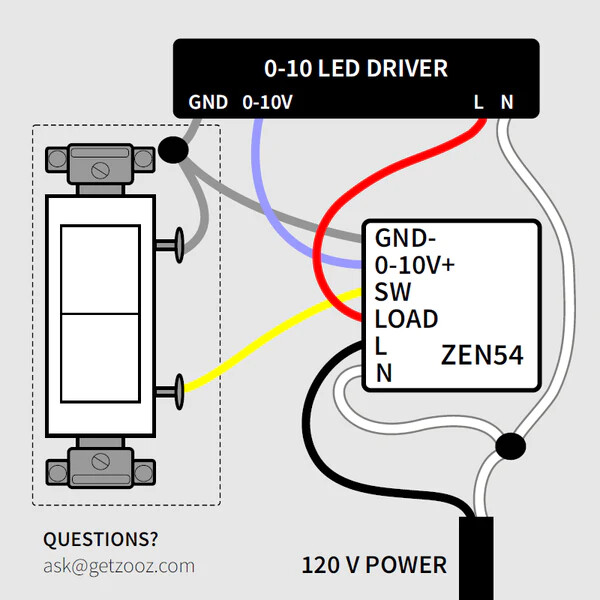
Turns out that outputting 171 watts of heat to my inline PTC heaters does indeed raise the temp from 58 to 68 F. Increase the CFM, or lower the input temp and more watts are needed. I scratched my head a bit on how to turn this information into a few automation rules that would set the Zooz dimmers connected to the heaters based on live data.
The dimmers use a setting from 0-100 so I needed to figure out how many watts the heaters used at each dimmer setting. I took about 10 measurements using a kilawatt type meter. Then I plotted those points to find that the dimmer/vs watts relationship was pretty linear. This link allows you to enter a few points and derive a simple equation for that relationship...you'll see it pre-populated with my two reference points:
This slope calculator solves for parameters involving slope and the equation of a line. It takes inputs of two known points, or one known point and the slope.
DIMMER SETTING = 0.122 * WATTS + 16
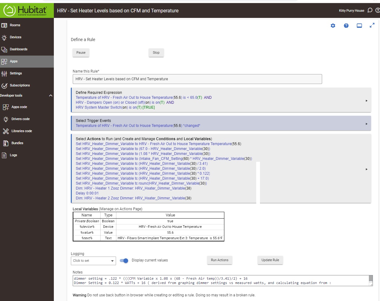
So combining the formula for watts and the dimmer, now I had a formula that would tell me what dimmer setting to use for a given wattage. The /2 in there is because I have two heaters so each will get half of the total wattage requirement fed to them.
DIMMER SETTING = .122 * (((CFM x 1.08 x (Temp Delta))/3.41)/2) + 16
Hubitat variable math does not do brackets (I think???). In Webcore this would all be one line of code, but here is what it looks like as you step through the calculation above using Hubitat's built in Rule Machine:
I may not even understand all this in a month, but I do think it's kind of cool that the heating system is continuously varying the heat output based on live measured conditions and the desired end result. It's a simple predictive system.
To my surprise, it actually works and the output temperature stays within a pretty small window of 1-2 F. In cold temps the system needs to stop every 30 minutes and recirculate air to warm the core up. When it goes back into ventilation mode (starts pulling cold air in again), the incoming air steadily drops as the heat exchange core cools. This heating setup compensates for that quite precisely and sets the heater wattage at exactly what it needs to be set at to get 67 F fresh air dumping into the main living area.
This is the code that switches up the EC fan speeds based on Co2 detected:
 It’s nice to hear from someone on the same wavelength!