I have some switches that aren’t wired for neutral, and I wanted digital switches to control my lights.
I decided to use SmartThings buttons to communicate between my Leviton switches, which aren't wired up to mains power. The lights themselves are always on. It feels nice to have a hub that's so reliable—I don't worry if pressing the switch will work or not, which isn't something I've said about other hubs or platforms in the past.
If this type of post isn't allowed, please let me know. Just figured I'd share my story of creating some unpowered wall switches with these buttons.
The teardown...
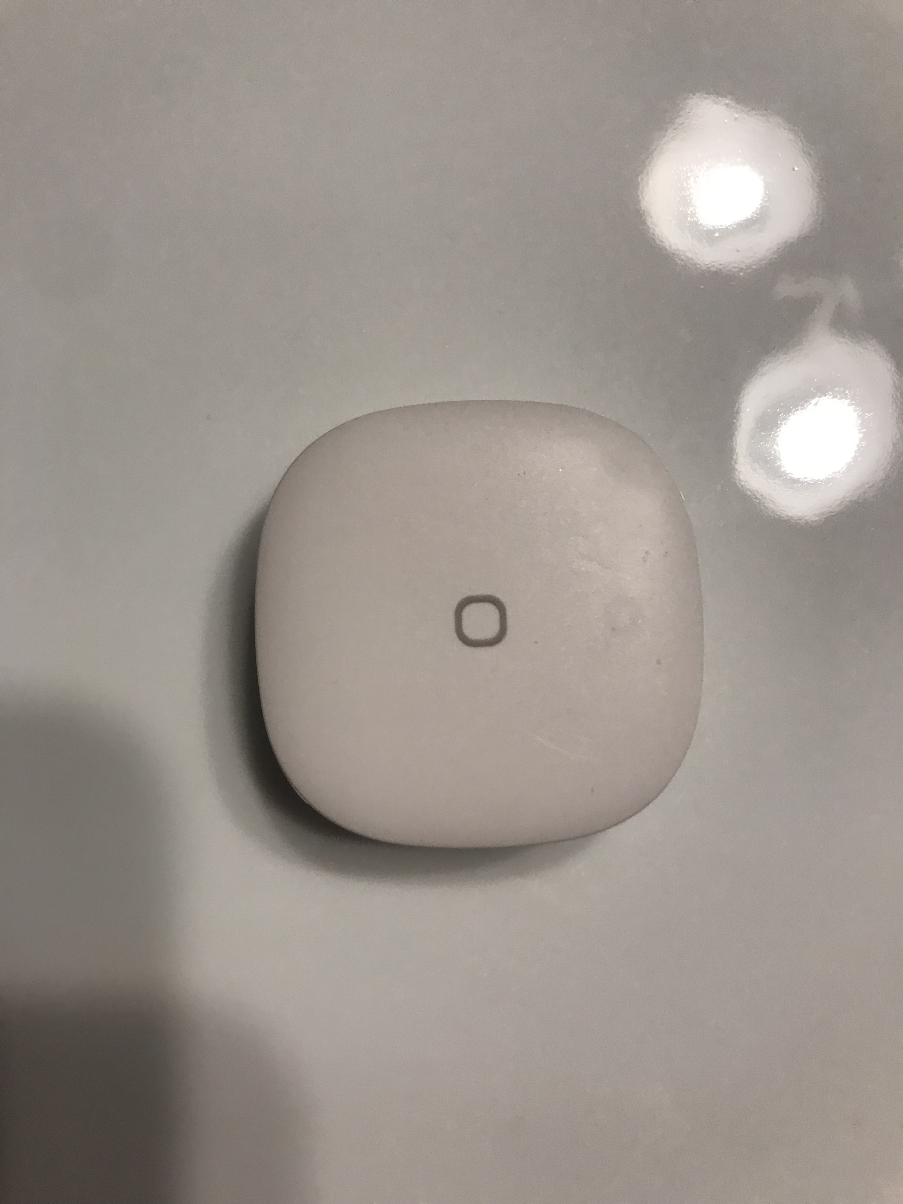
The buttons themselves look pretty nice. The click feels good, as well!
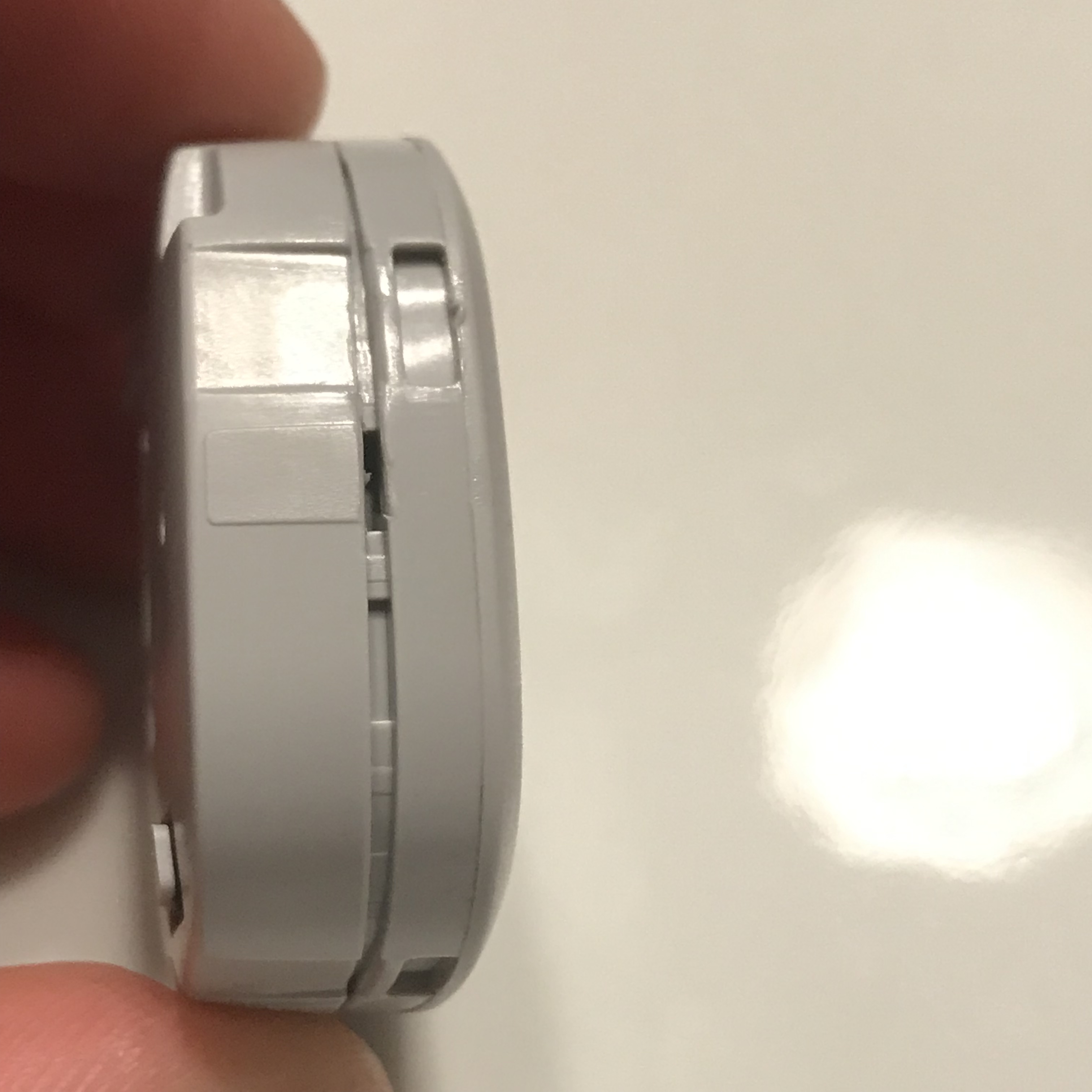
Prying off the front plate is somewhat easy. There are plastic tabs that create the forward tension for the button.
The cat wasn't happy that I was working on her table. 

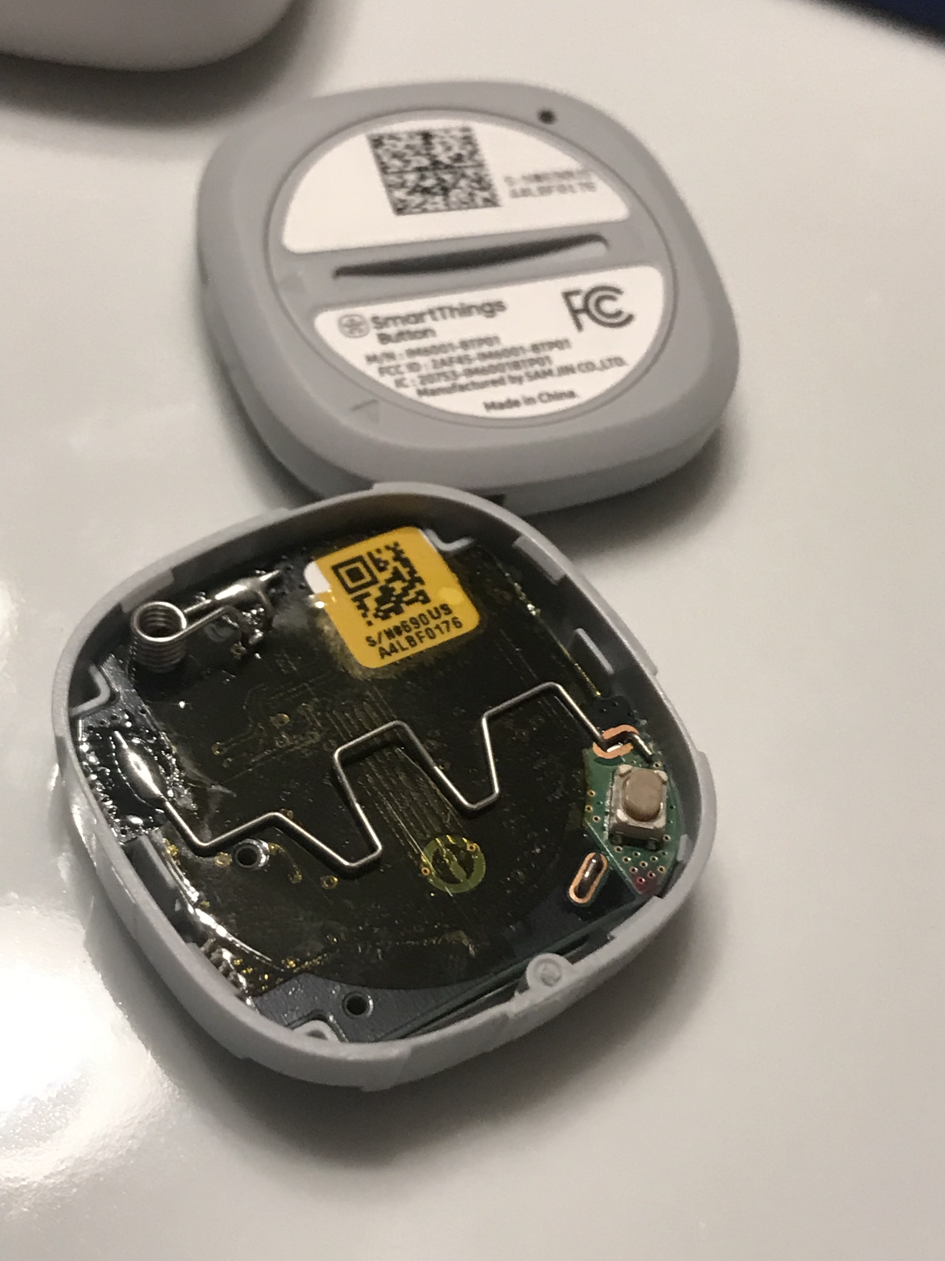
The buttons are held together using plastic clasps. A metallic spudger worked just fine to pry it open.
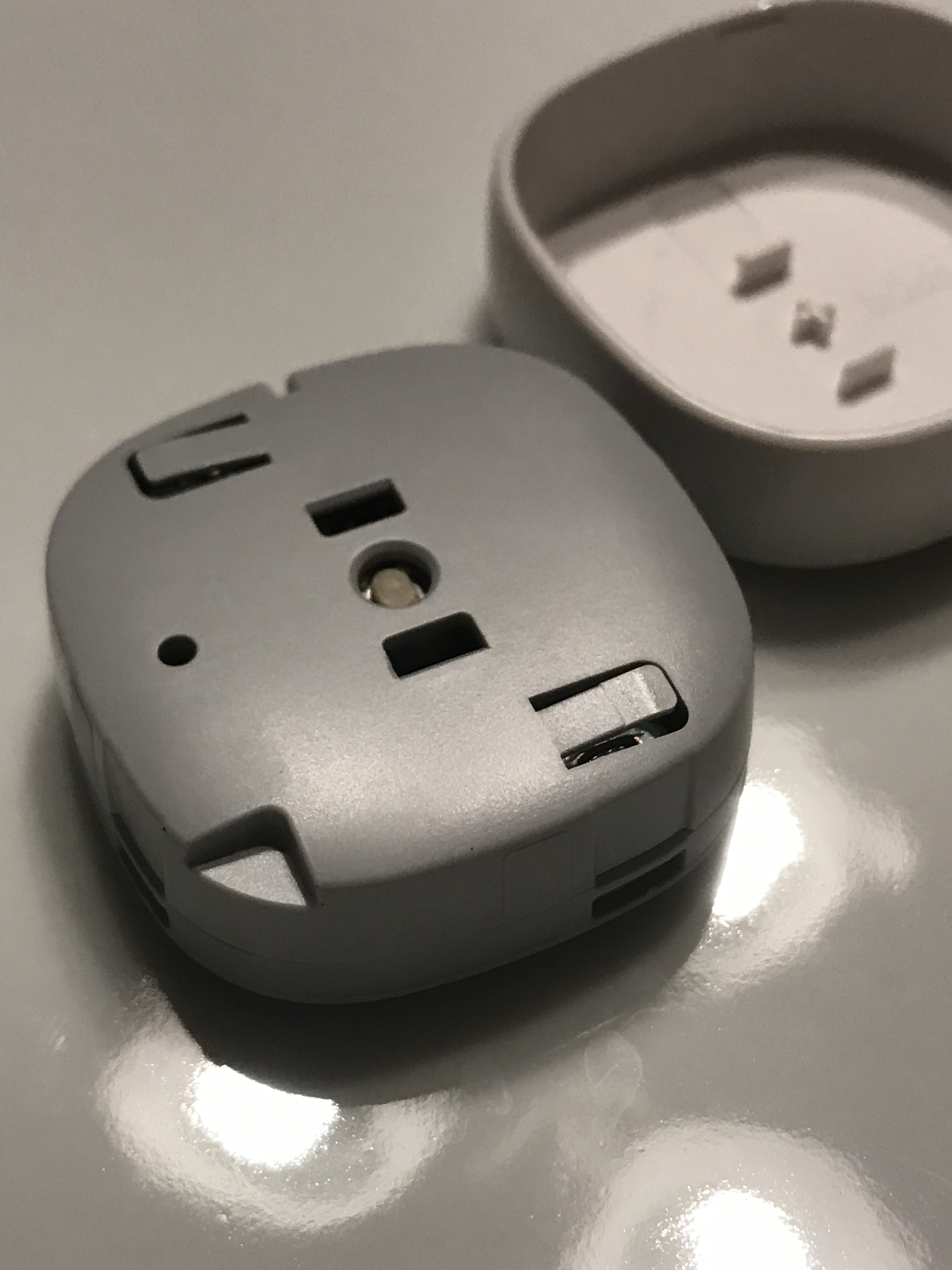
On the back side of the device, you'll notice a battery door (that can be opened with a coin) and a reset button.
The battery itself is actually held in with a magnetic back--what a good idea! The underside of the battery connects to this wire to complete the circuit. You'll also notice a coil on the top (to connect the positive terminal of the battery) and a button on the bottom --- which is what is depressed through the pinhole on the back of the device.
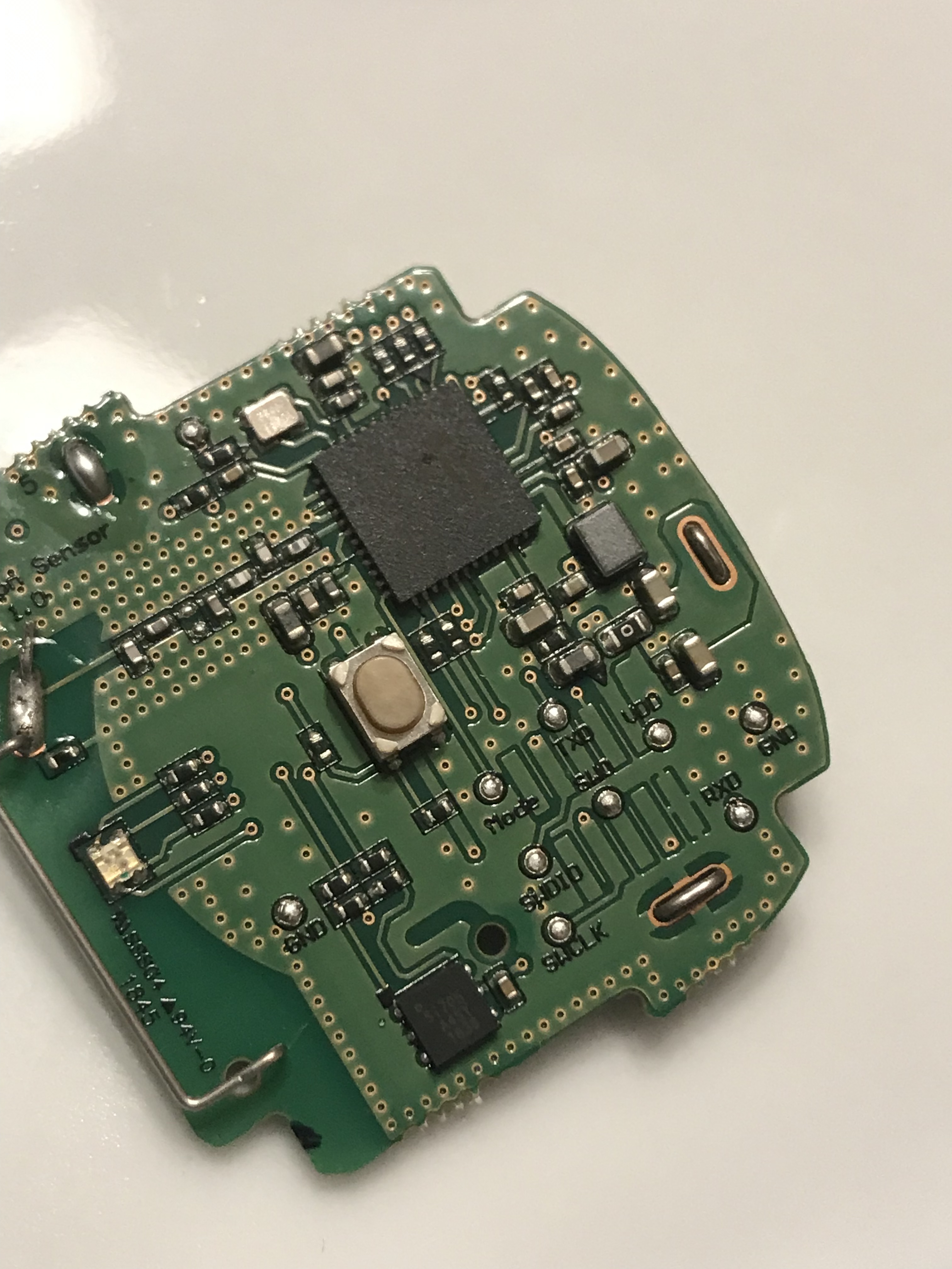
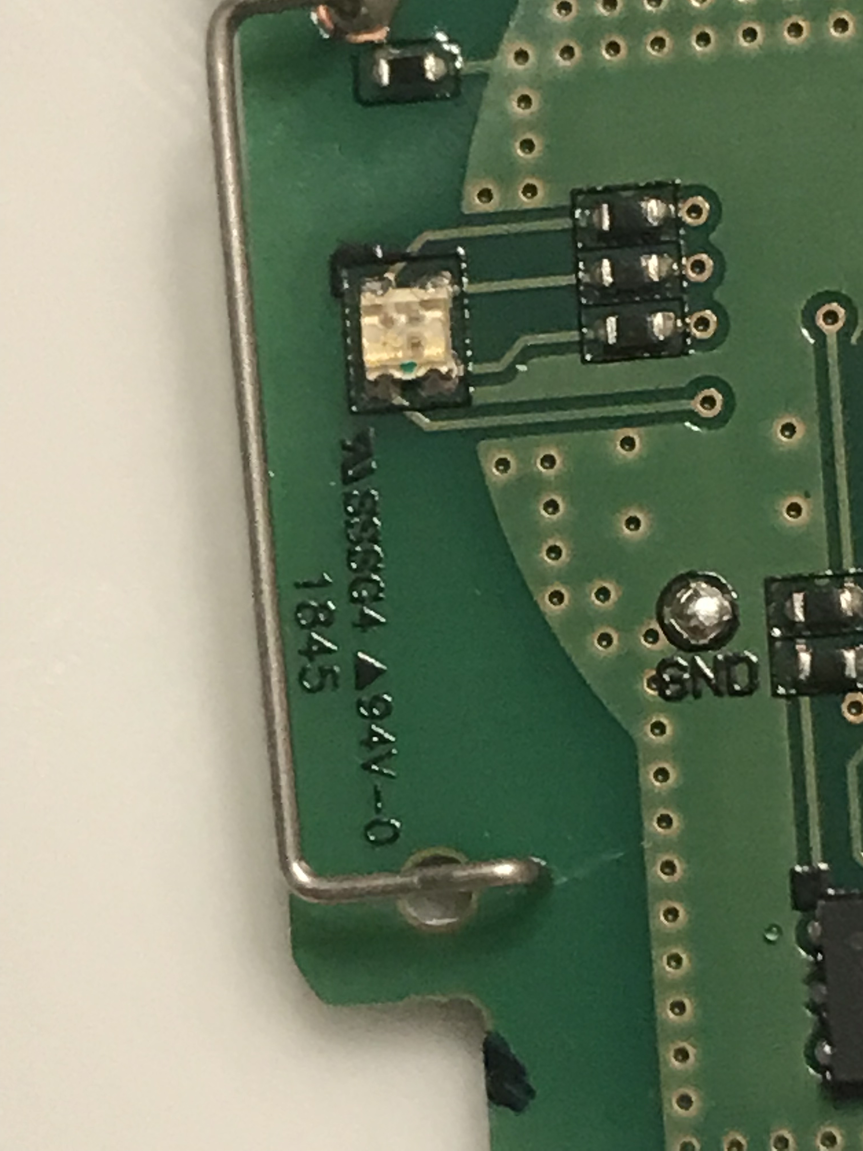
The opposite side of the board reveals the button itself, in addition to an LED. Nothing too strange here.
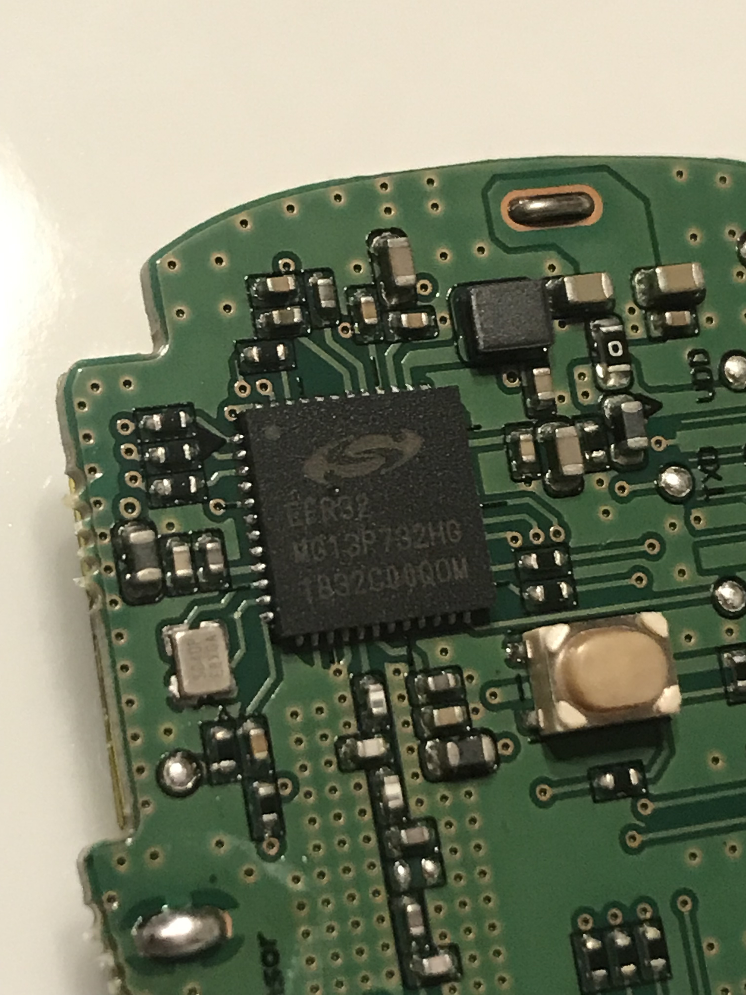
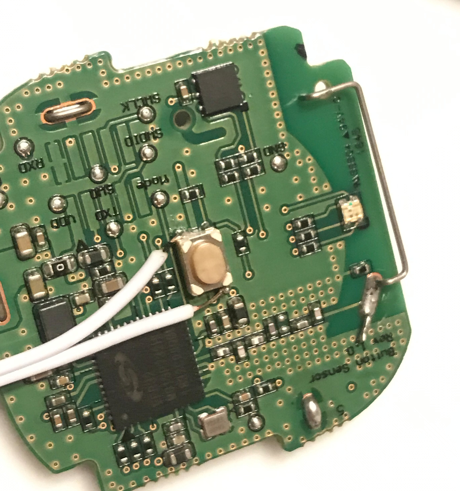
This chip reads
EFR32
MG13P732HG
1832C00QOM
I haven't looked into it at all, yet.
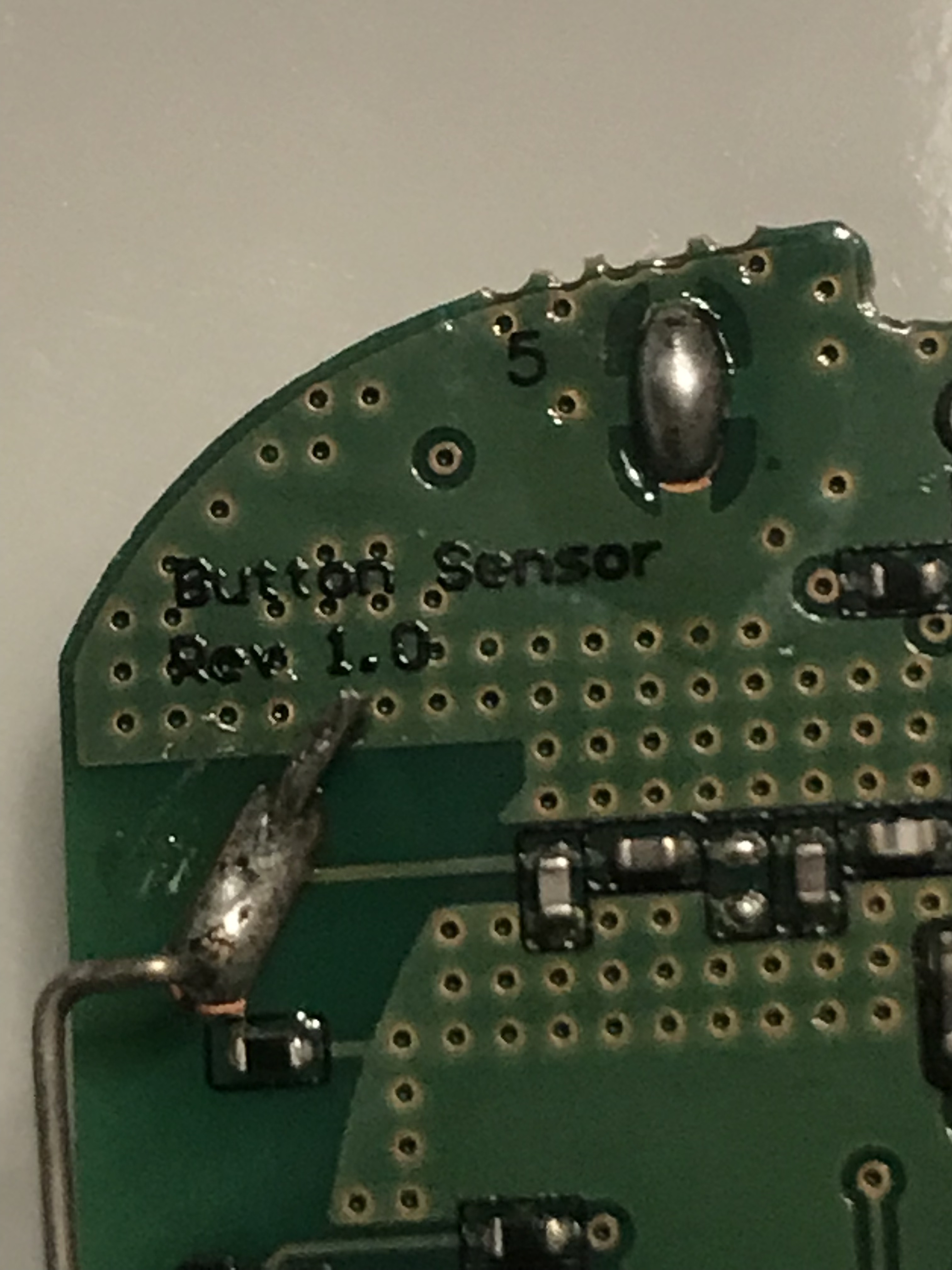
Looks like I have the first revision of the sensor. I do wonder what future revisions will have changed.
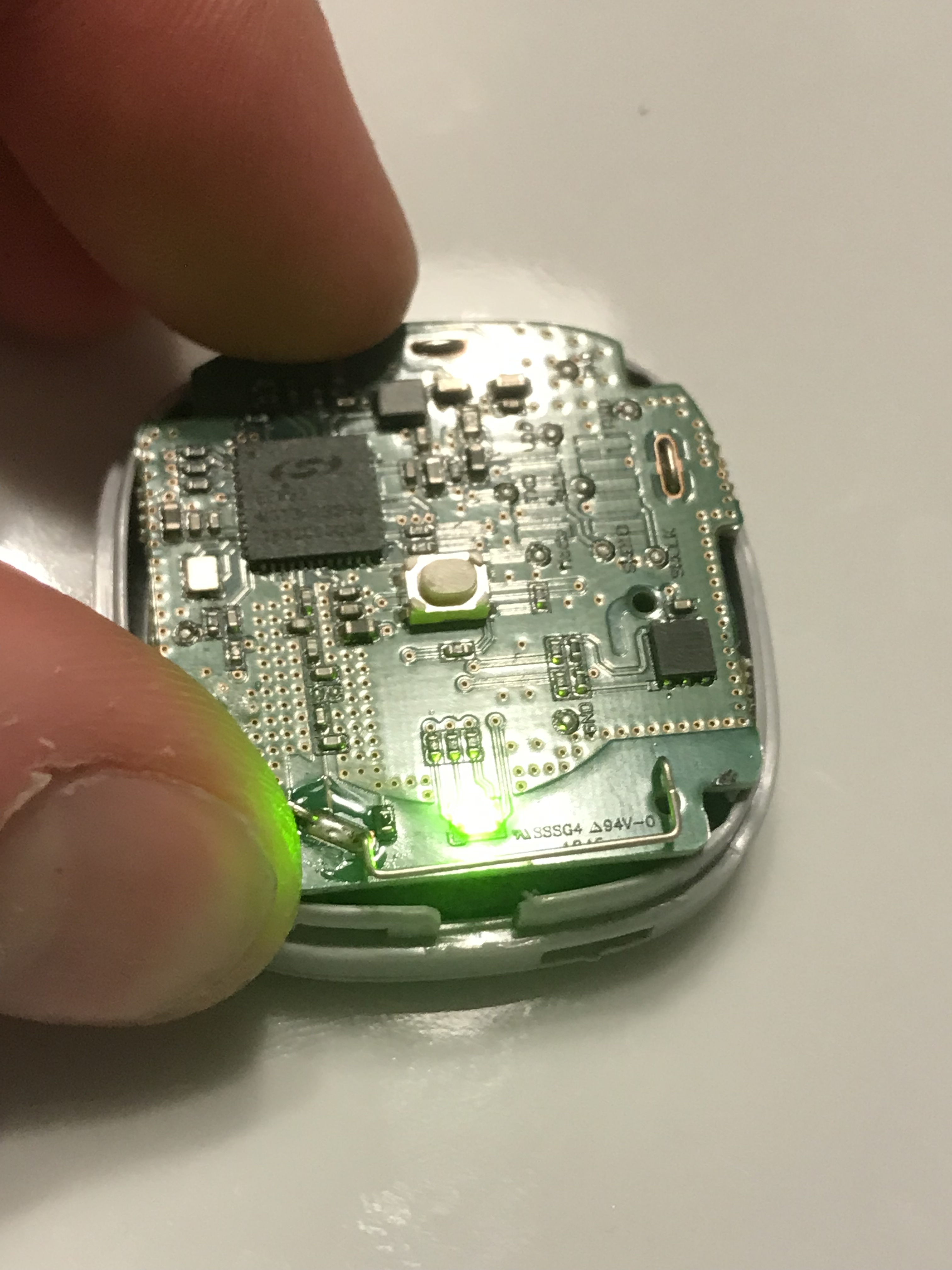
The LED seems to be RGB. I haven't tested for voltage or anything, but I may revisit this in the future.
I figured I should probably make sure the board still works, at this point.
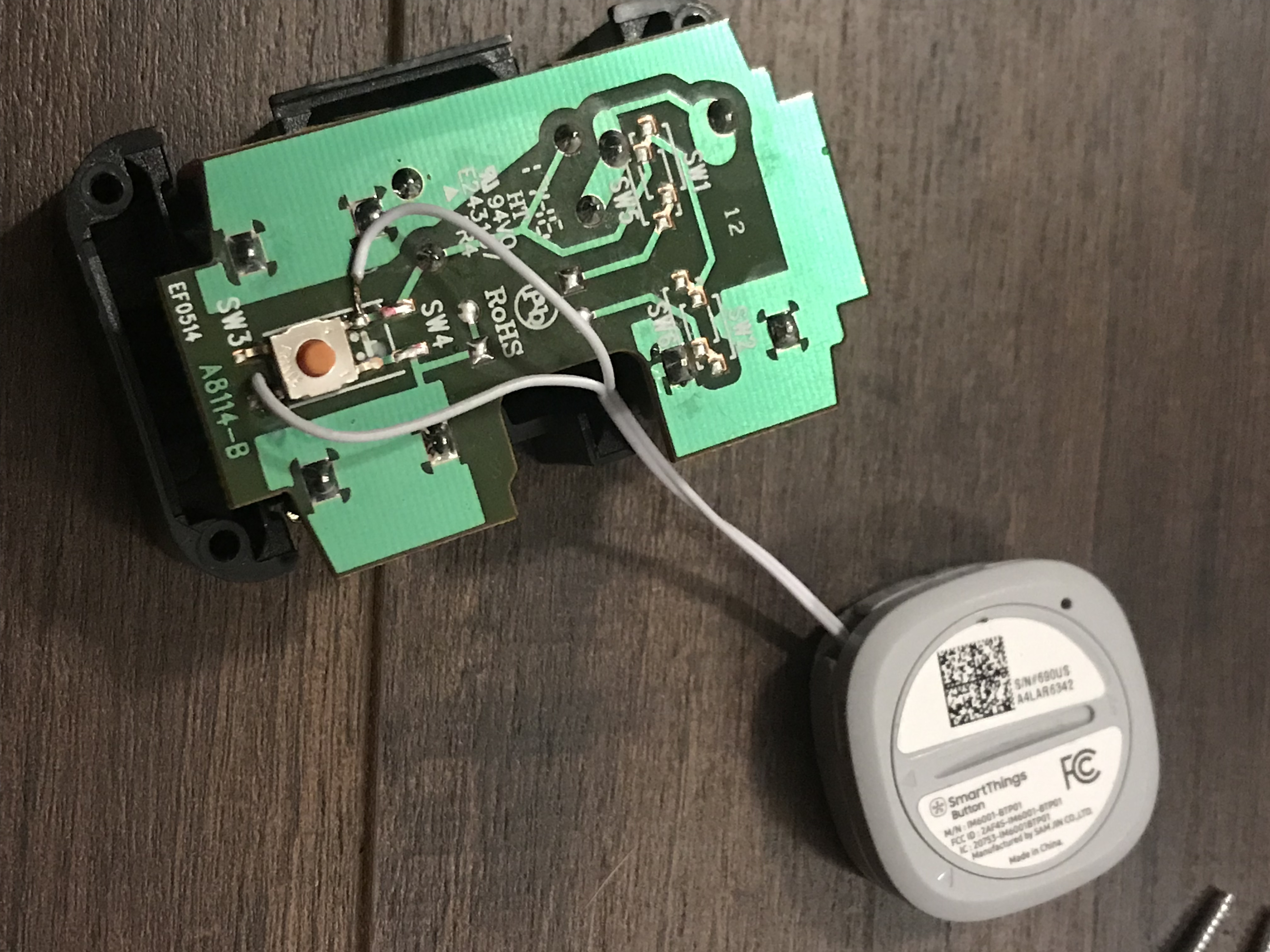
The next step was to solder my connection wires to the button contacts.
How does the soldering look?
 My best soldering work
 Not my best soldering work <<< Survey says
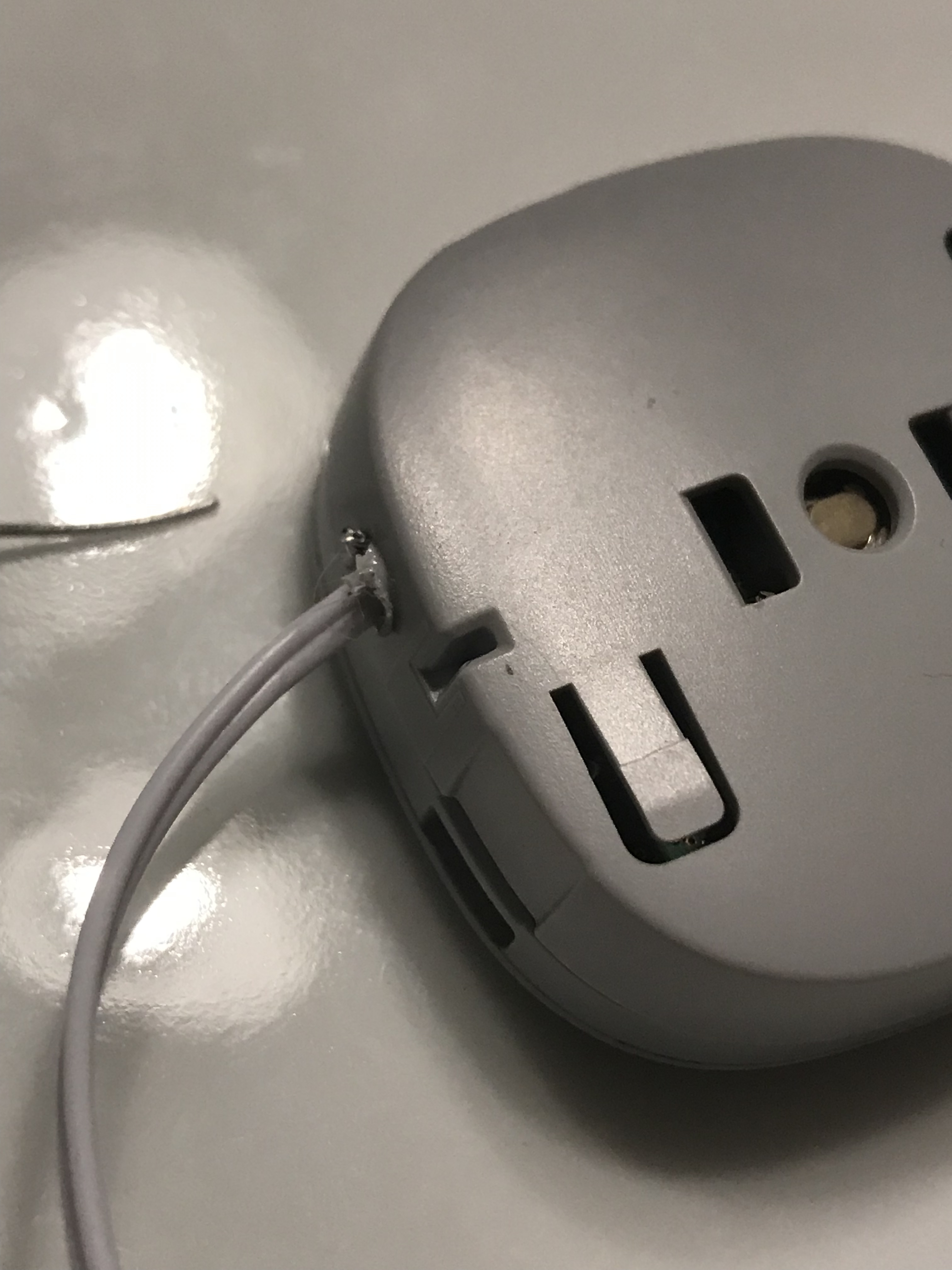
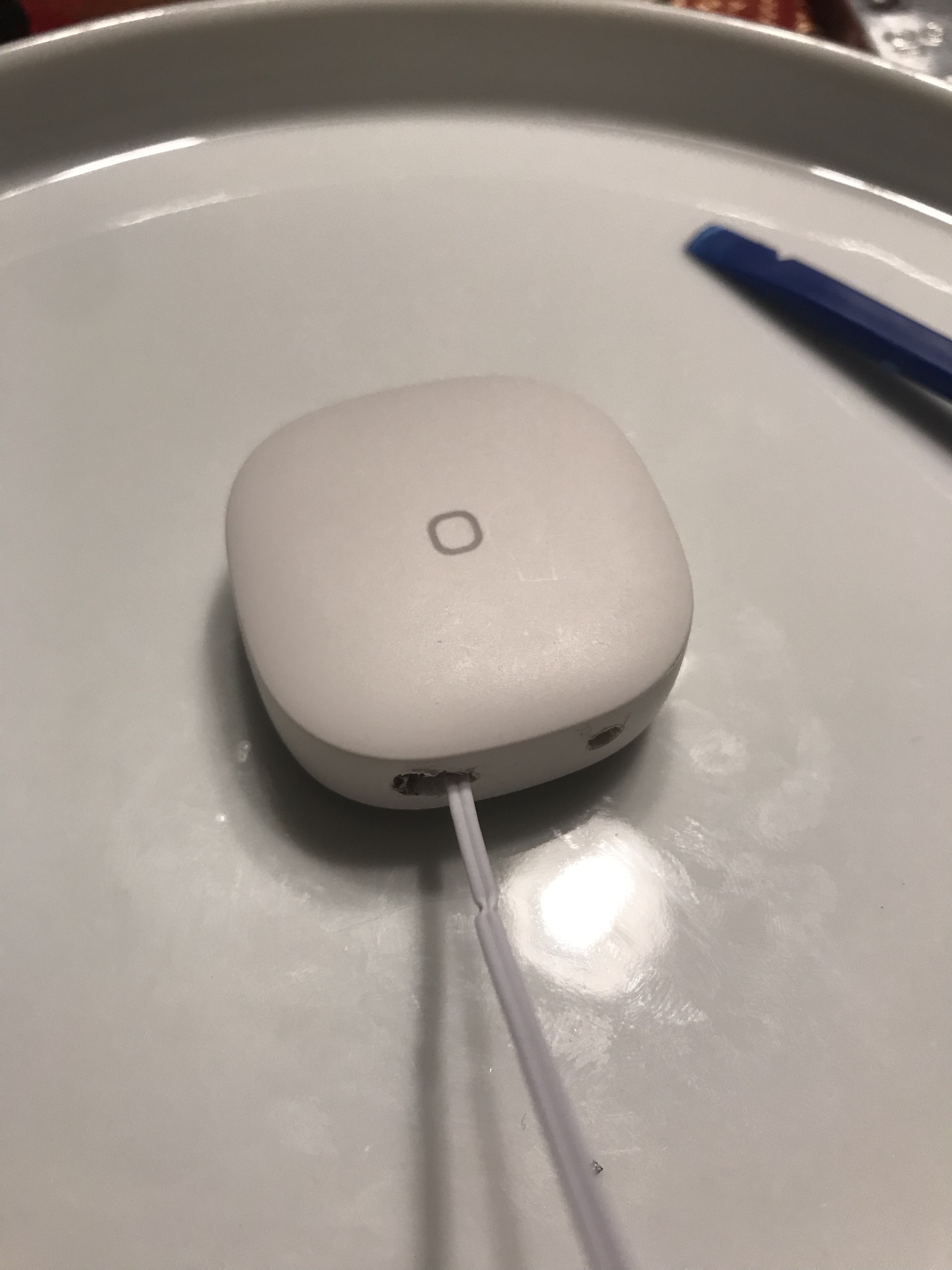
And then route the wire through a melt-cut hole.
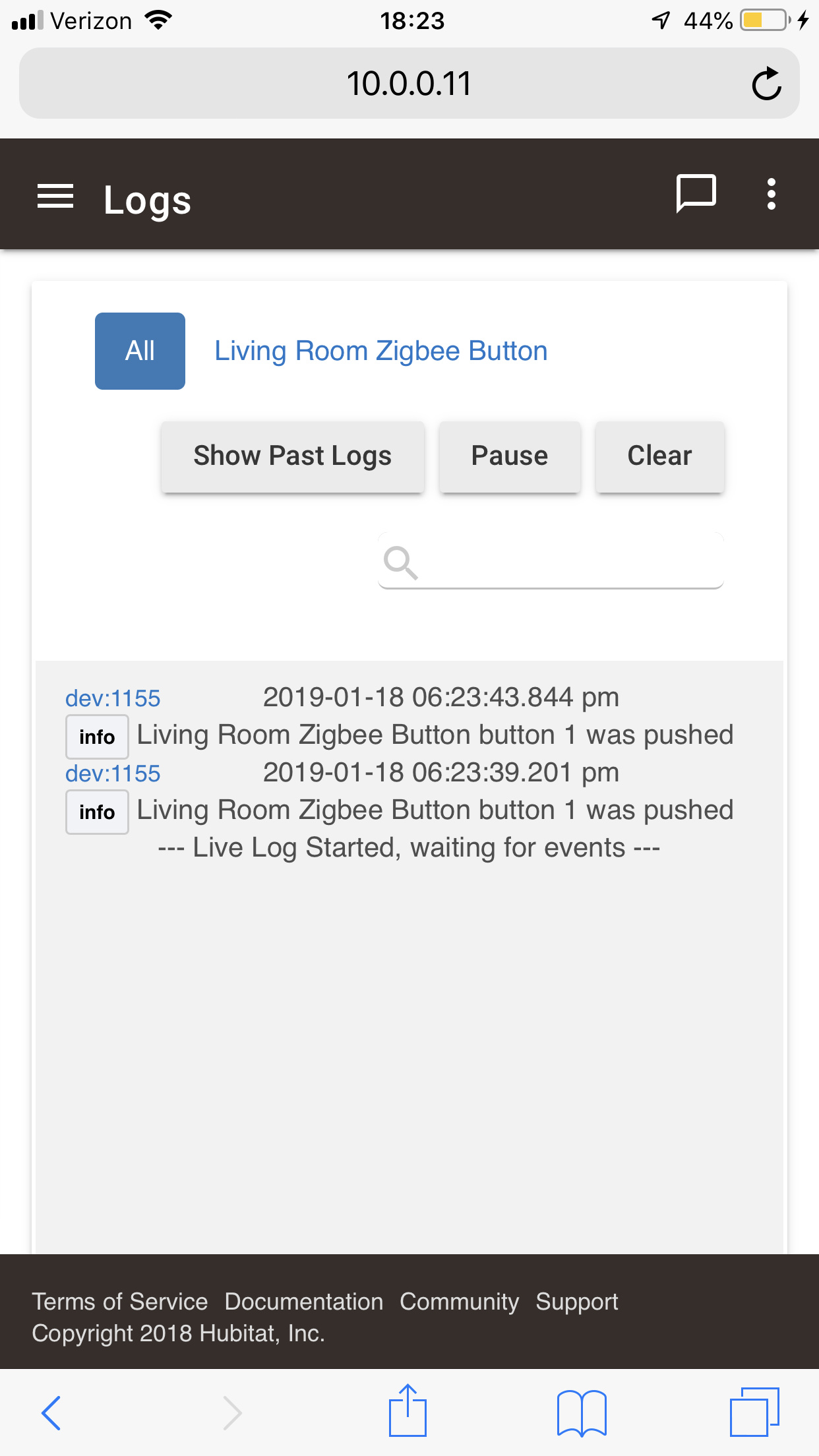
Finally, I tested the contacts in HE to ensure they'd work as intended (they did).
And then, I re-assembled the unit. I kept messing up my cutting, but got it right in the end.
I soldered the other side of the wire into a non-smart Leviton Decora switch. These are my favorites, and a few friends have commented on how good they feel to press (which, we honestly don't do a lot thanks to presence sensors.) One day, I may revisit wiring the LED from the button to the switch, but for now, it's nice to only have 3 switches in the entire house that aren't smart. 
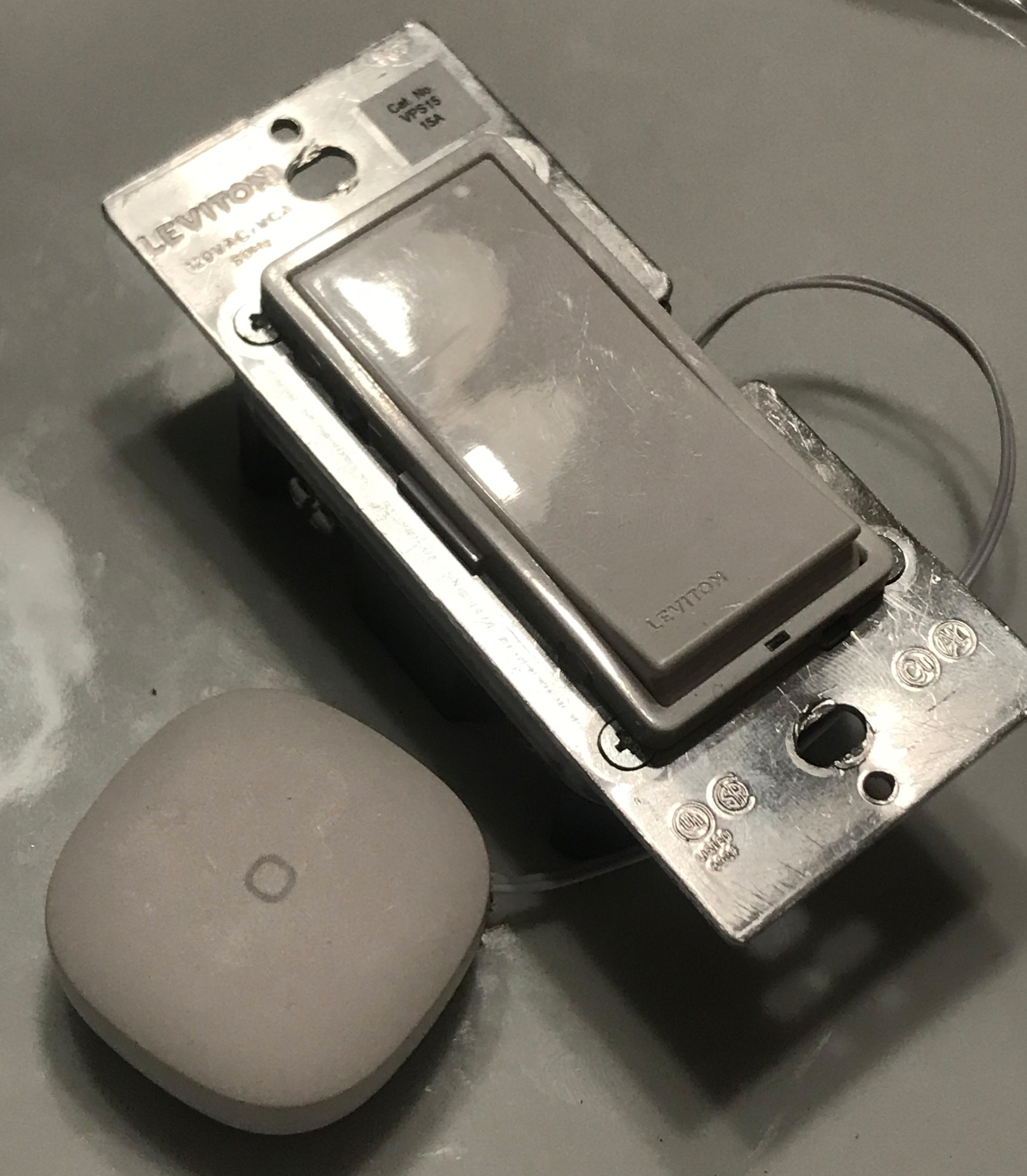
Here’s how the switch itself is wired. NO wires go to the mains.
 (Or I guess maybe box the "dumb" switch used to be in with everything capped, but I'm not sure about mixing that with some sort of barrier.)
 I can add a wiring diagram if that will help


