Here’s a fun hack for mounting a Z-Wave sensor in the jamb of a sliding door to detect locked/unlocked status.
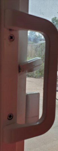
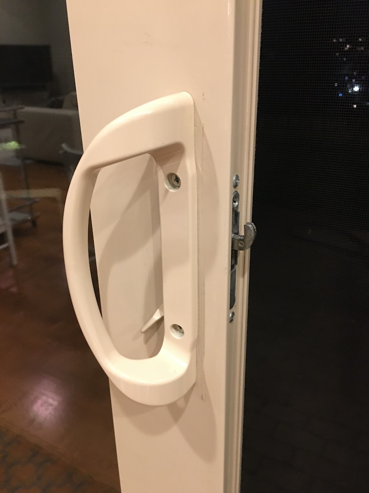
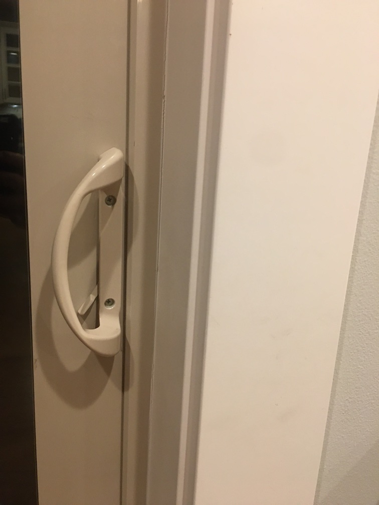
We sometimes forget to lock our sliding patio door, as the lock lever blends in behind the handle. Earlier this summer, we were woken by the burglar alarm when a prowler opened the unlocked door. Fortunately the alarm scared them off. It got me thinking though: how to add a lock-status sensor to give us peace of mind, with Hubitat alerting us if we go to bed or leave the house without locking up, and Alexa responding to "Is the patio door locked?”
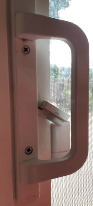
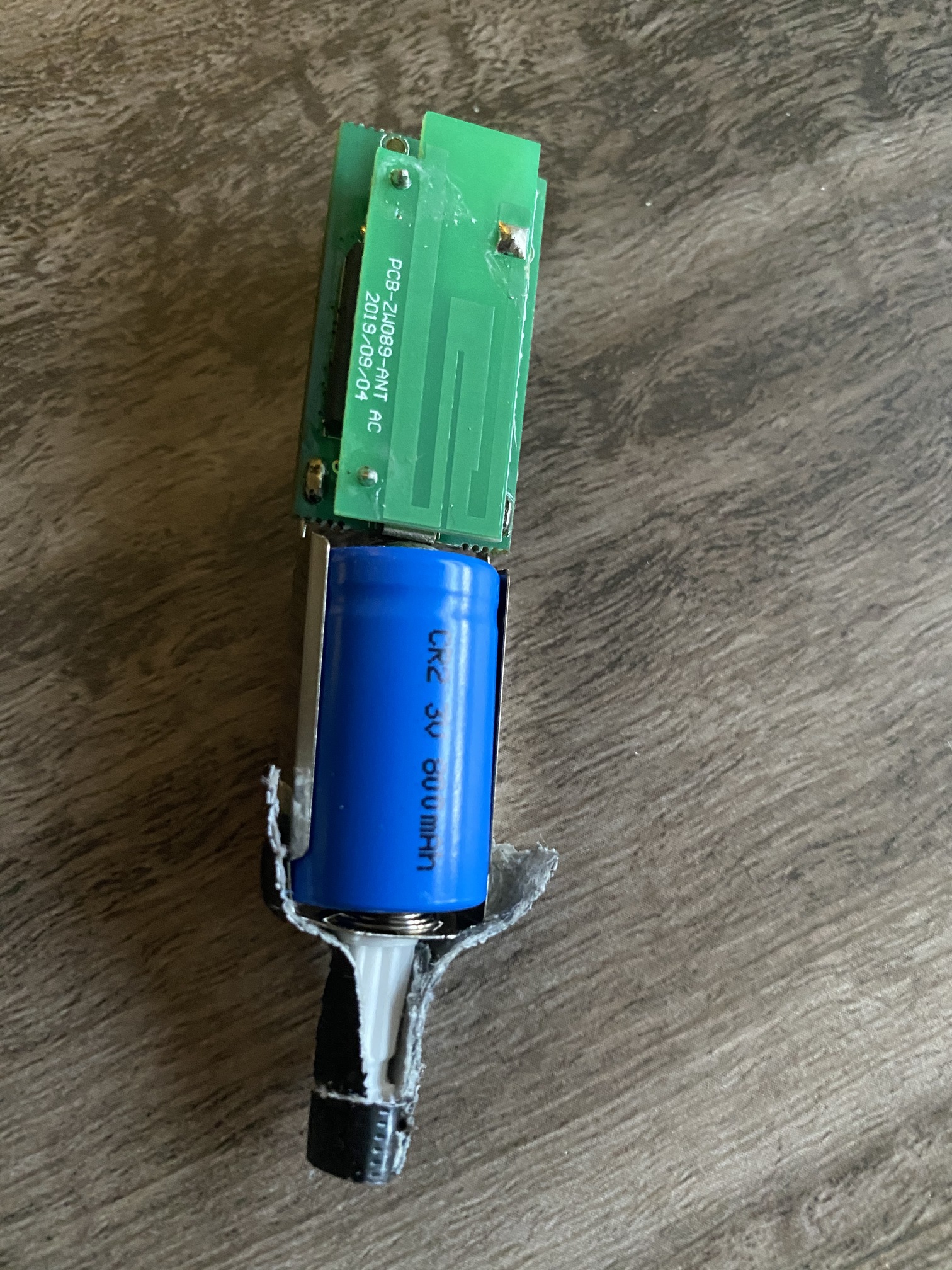
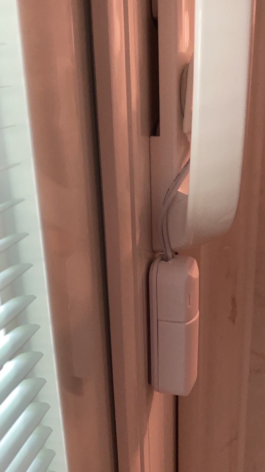
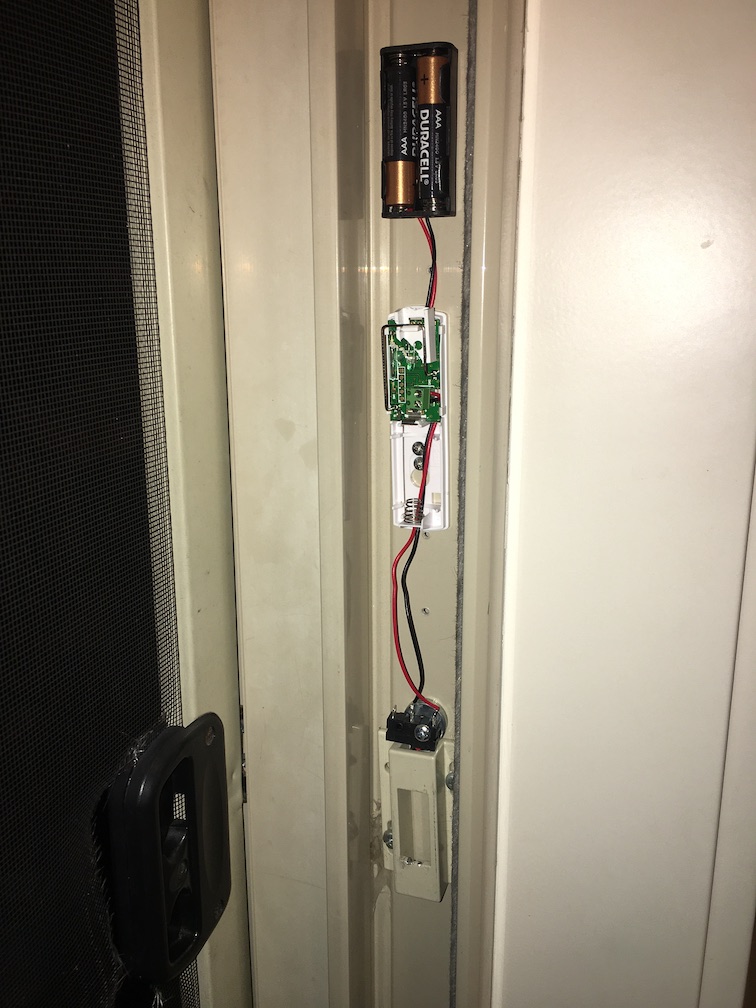
I found a solution on the Smartthings community that involved screwing a bulky dry contact sensor onto the door or door frame, wired to a microswitch. I wanted a sensor that's hidden when the door is closed. So I borrowed their idea and slimmed down a 25mm-high contact sensor to 13mm, to fit into the 15mm deep gap in the door jamb.
Thought I'd share here to give back to the community boards that were so helpful to me when I first got started. Let me know if you want more detail on the hardware or Hubitat config.
Jedi skills. I can only dream of such. Is that a Zwave GoControl sensor, or ?
I will NOT be showing your cool approach to my wife, if you don't mind, as there will be a lot of "Wow, why didn't you do it that way?!" comments that I will end up on the wrong side of.
My low-tech approach below using a slim Visonic contact sensor and magnet mounted on lock lever. Works, but wife's comment was "Well, I guess it's not too ugly like that."
That was my buddie's suggestion, replace the lever w/a magnetized lever. However, I'm the guy who takes things apart, reassembles them, and then finds two or three pieces "left over" that didn't get put back in. Safer if I keep it simple...
I actually prefer @jason5's approach, and am going to see if my unused GoControl sensors can be put to use w/his method on one of my sliding doors that I don't have a lock sensor on. If I can find a way to hide the hardware (white tape? piece of white plastic?) It might get wife approval. Will not fly if the battery and sensor, etc., are visible in the jamb.
I actually need to replace the way too old to find parts for lock and lever for my door with something newer. But this makes me want to verify I can add custom bits and bobs to it!
Just replace it with french doors. That's what I did and now I can open both sides on a nice day and have 6 feet of screen. It's just like being outdoors, except with a flat screen and leather couch.
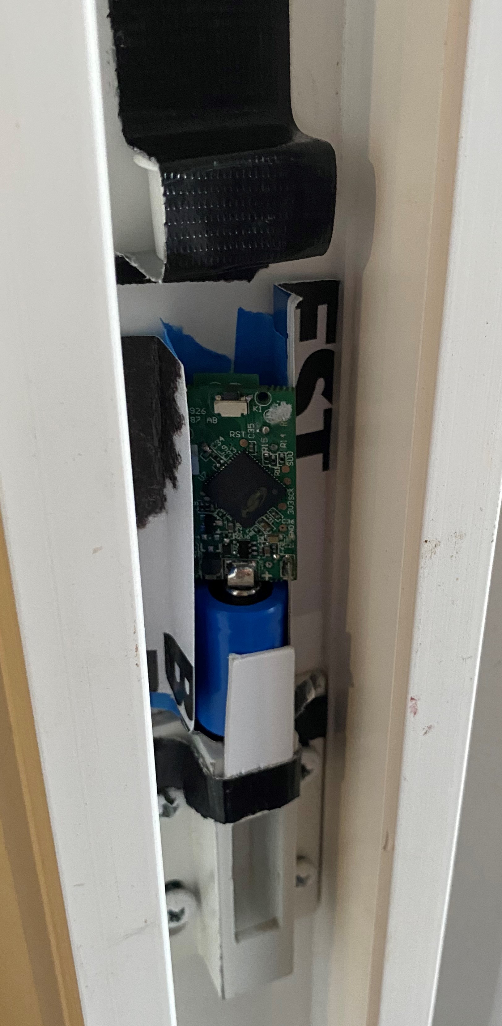
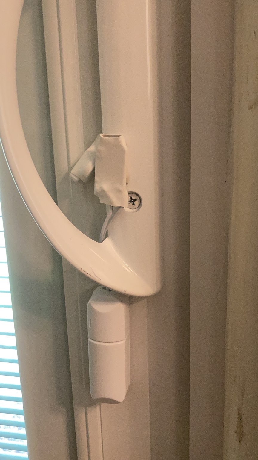
My main tips for anyone who tries this is are to (1) figure out early how you'll close the Ecolink's tamper switch, as that's the fiddliest part of this project (I cut down one of the plastic parts that came with the Ecolink, as it was the perfect height to slide under the antenna and close the switch), and (2) mount the Z-wave antenna away from the metal door handle. My first attempt had the antenna level with the door handle and it lost signal when the door closed.
If I was doing this project again, I'd probably mount the dry contact sensor and batteries below the lock to make them less obtrusive, unless I had very small children. But too late now. Besides, it's less noticeable in practice than my photo suggests, as the door jamb has a deep flange and you rarely look to the side as you walk through the door; I hadn't noticed the alarm sensor that's in the same jamb before I did this project.
@jason5 this looks exactly like something I want to make. I understand from your posts the general concept you have achieved. Also understand that getting the microswitch placement solved so that the physical movement of the lock closes the circuit is going to be the trickiest part. (I need to think about this!)
The bit I could do with some help with is how you get the Ecolink (or any type of contact sensor) to close without using the usual magnet method. How does the wiring work to simulated closure?
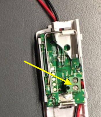
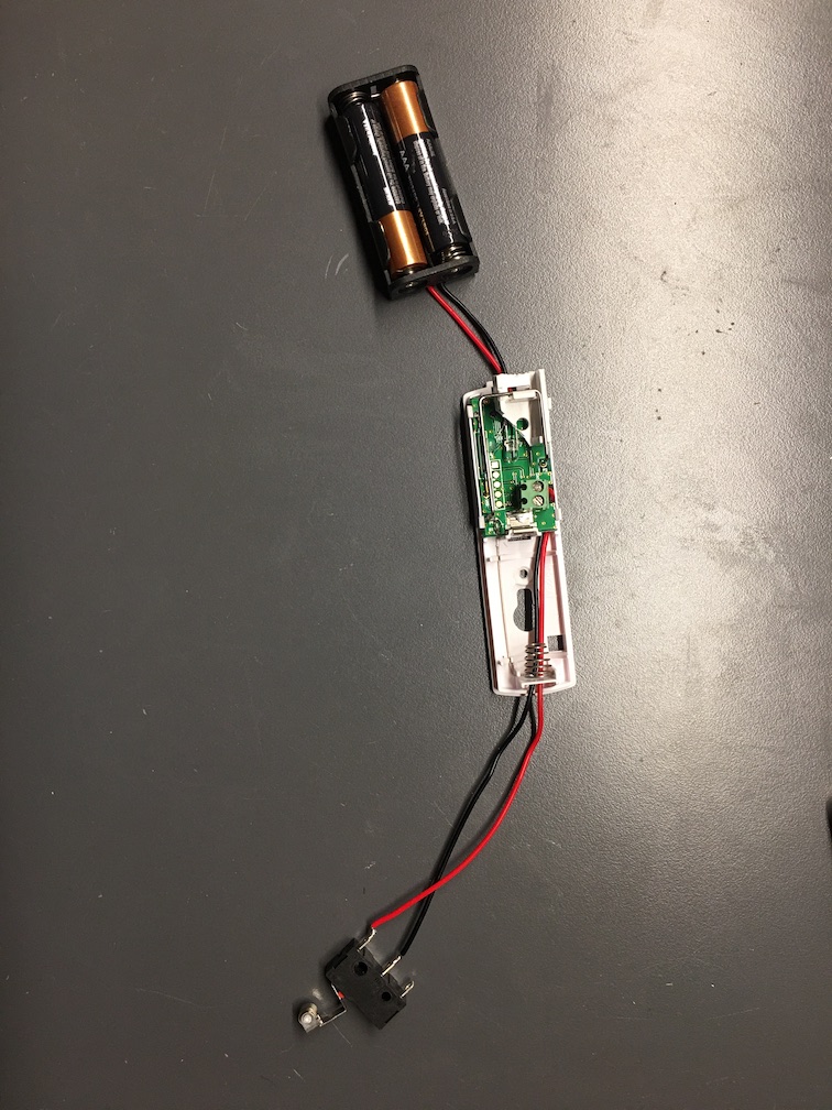
Most contact sensors contain a reed switch, which closes the circuit in the presence of a magnet and opens when the magnet is removed. To modify it to work with a microswitch, you wire the microswitch in parallel to the built-in reed switch. Some sensors including the Ecolink offer wiring terminals for this purpose (see yellow arrow on this photo):
So I just connected the 'NO' (normally open) and 'C' (common) terminals of my microswitch to the two screw terminals. If you look closely, you'll see the black and red wires for my microswitch emerging on the right hand side of the screw terminal block. They then tuck under the corner of the circuit board before exiting the bottom of the photo towards the microswitch, to reduce the risk of a wire breaking at the screw terminal.
The same concept applies for contact sensors that lack screw terminals, but you then need a small soldering iron and a very steady hand to solder the microswitch across the ends of the reed switch.
Fantastic @jason5! Thanks for the explanation. I have ordered the bits so I will let you know how I get on. I'm in CA so it's a nice lockdown project! (pardon the pun)
I am also thinking about ordering some tiny neodymium magnets to see if I can get the contact sensor working with them as an alternative. Some how attaching the magnets to the lock mechanism (assuming I have enough clearance) and arranging the sensor in a way to recognise them.
I notice on your battery pack that you have not wired it to the existing battery terminals? Is there a reason for that and where did you wire them to? Can't tell from the picture.
That would be a better solution if you can get it to work. I tried the same trick but couldn't find anywhere to attach them that didn't interfere with my lock mechanism's operation. YMMV.
I soldered my battery wires to the + and - pads on the back of the PCB where the existing battery terminals attach, as the pads are nice and large.
Soldering the wires to the PCB will be more reliable than on the terminals, because of the zinc plating on top of a flexible metal makes it very hard to keep a good connection when soldering to it. Always go for the PCB when you can, if you can't, do what you have to do to keep that WAF high
I was able to use an Aeotec recessed door sensor 7 to show the status of my patio sliding door lock. I took the main sensor out of the case and glued/taped a skinny plastic piece i found laying around the house to the bottom. That skinny piece slides down into the top of the keeper. When the door is locked, the latch pushes the sensor up toward the magnet which is under the black tape at the top of the picture. When it is unlocked, the sensor falls down away from the magnet. I had to sand down the plastic casing of the magnet just a bit so the door could close all the way. I used some card stock as a guide to keep the sensor in place. There is an Inovelli switch right next to it that is configured to show the status of the lock. It has been 100% reliable once I found the sweet spot to place the magnet. My next step is the hide all of the components for WAF.
That’s genius! Super simple. It should also be more reliable than my original design, where the microswitch needs occasional realignment. I may copy this.
I am going to necropost this one just to show my take on this!
I separated the innards from a centralite contact sensor and wrapped them in white heat shrink and then attached the magnet with heat shrink to the lever.. reused the battery compartment as well
 I can only dream of such. Is that a Zwave GoControl sensor, or ?