Background :
I had been looking for a way to shut down and restart my Hubitat hub in case of a power outage. The hub and all my internet equipment have some form of backup power but they last anywhere between 30 minutes to about 90 minutes. I looked at Ring Range Extender but while I could shut down the Hubitat hub using RM in case of a power outage, I still needed a solution to restart the hub when power came back on. I came across a discussion on the Kasa (TP-Link) plug in the Node-red forum and that sent me down this rabbit hole…
If you have any suggestions for simplifying or improving this (or any flaws in my logic), please let me know. I hope this helps someone down the road.
If you would like the actual flows, please PM me – I need to clean some of my network information etc. that is in the code.
Hubitat Power Outage Management Flow:
Flow logic:
Determine if there is a power outage and shut down hub:
- Use node-red to periodically ping a device not connected to a UPS (STEP 4)
- If device does not respond (power failure), ping a second device just to confirm that there is a power outage (STEP 5/6)
- If second device does not respond, assume that there is a power failure (STEP 7)
- Ping Hubitat hub to confirm that it is up (and wasn’t already shut down) (STEP 8/9)
- If Hubitat hub is up (responds to the ping), shut down the hub.
- If Hubitat hub is down (does not respond to the ping), assume that power is still out and hub was shut down previously
Determine if power is on and restart hub if it was shut down:
- Use node-red to periodically ping a device not connected to a UPS (STEP 4)
- If device responds (no power failure), ping Hubitat hub to confirm if it is up (STEP 11)
- If Hubitat hub is NOT up (it was shut down previously), restart the hub (STEP 12/13)
Miscellaneous logic:
- If the first device pinged does not respond, but the second one does, there is no power failure and the first device did not respond to the ping for some reason (STEP 6/7)
- If other maintenance flows (hub reboot, backup download) are executing, a “Control” gate is “closed” (using the Link-in node) in order to prevent this flow from trying to restart the hub (STEP 3).
- When the other maintenance flows are finished, the “Control” gate is “opened” (using the Link-in node)
Prerequisites
- At least 2 IP components with static IP addresses that are not plugged into a UPS (NOTE: I use 2 Harmony Hubs)
- Hubitat Hub with static IP address
- Kasa (TP-Link) HS105 wifi plug (https://www.amazon.com/TP-Link-Occupies-HS105-Wall-Light-Electronic-Component-switches/dp/B01K1JVZOE/). Assign a static IP address to the plug (NOTE: I use this plug as there is a node-red node to control it. If there are any other wifi plugs that can be turned on/off from Node-red, you should be able to use those instead)
- UPS (or some battery backup) for Hubitat Hub, Node-red server and Router
- Pushover account (https://pushover.net) for receiving notifications
Node-RED components
Hubitat Power Outage Management Flow :
- Standard nodes – inject node, ping node, switch node, link-in node ,
- Extra - node-red-contrib-simple-gate (used for suspending flow while other scheduled maintenance flows are executing)
Shutdown Hubitat subflow:
- Standard nodes – http request node function node ,
- Extra - node-red-contrib-moment (used for formatting date/time stamps for notifications)
Hubitat Login subflow :
- Standard nodes – http request node function node, change node
- Extra - node-red-contrib-credentials (used for preventing username/password being exported with flows)
Restart Hubitat subflow :
- Standard nodes – ping node, switch node, change node, delay node,
- Extra - node-red-contrib-tplink (used for controlling Kasa HS-105 plug ), node-red-contrib-moment (used for formatting date/time stamps for notifications)
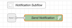
Notification subflow:
- Standard nodes – pushover node (the only reason I use a subflow for this is to avoid having the Pushover User Key and API Token in multiple places)
Hubitat Config:
Security enabled (username/password) (NOTE: This is not a requirement and you can adjust the flows to remove the login components).
Flow/Node Config :
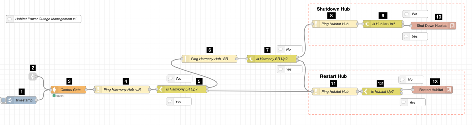
Hubitat Power Outage Management:
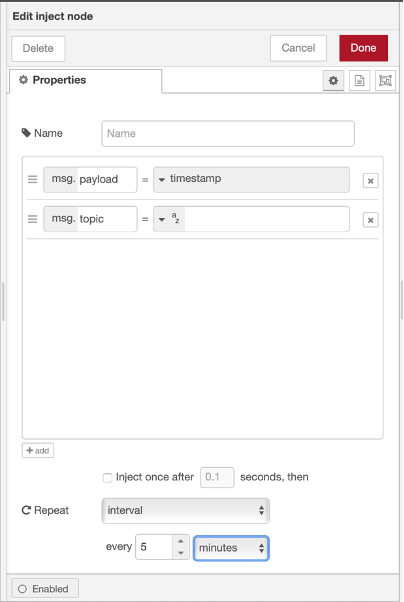
Step 1 : Inject node configured for scheduling the flow – I have it configured to execute every 5 minutes
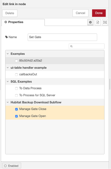
Step 2 : The Link-in node controls the state of the Gate node. It sets it to “close” when the flow has to be suspended and to “open” when the flow is to resume. There are corresponding Link-out nodes in the other flows that set the status.
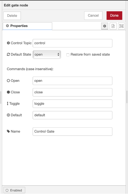
Step 3 : The Gate node is set to “close” and “open” to control the execution of the flow
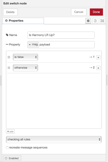
Step 4: The Ping node is configured to check the first device. The node returns “false” if the device is not reachable, otherwise it returns the response in milliseconds.
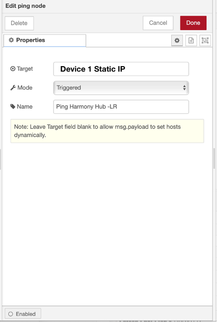
Step 5 : The Switch node directs the flow based on the ping result. If ping is “false” (device not reachable), the flow is directed to the secondary device to confirm if there is a power outage. If the device responds (ping is not “false”), device is powered and the flow checks to see if the Hubitat hub is responding.
Step 6 and 7 : These are very similar to Step 4 and 5. In Step 6, the Ping node is configured to ping the secondary device and Step 7, the logic checks if the secondary device responded to the “ping”.
If it did not (ping is “false”), there is a power outage and the flow goes to check if the Hubitat hub is up (Step 8).
If the device responds (“ping” is NOT false), then it is assumed that there is no power outage and the first device did not respond for some other reason. The flow then goes to check if the Hubitat hub is up (Step 11).
Step 8 and 9 : These are very similar to Step 4 and 5 except that the ping node in Step 8 is configured to ping the Hubitat hub.
In Step 9, if the Hubitat hub responds to the ping (“ping” is not “false”) the Hubitat hub has not been shut down and the flow goes on to start the shutdown process (STEP 10)
If the Hubitat hub does not respond to the ping (“ping” returns “false”), the Hubitat hub was shut down previously and the flow stops.
Step 11 and 12 These are very similar to Step 8 and 9 and the ping node in Step 11 is configured to ping the Hubitat hub.
In Step 12, if the Hubitat hub does not respond to the ping (“ping” is “false”) the Hubitat hub was previously been shut down and the flow goes on to the restart process (STEP 13). Since the other devices are responding, the power is assumed to be on
If the Hubitat hub does respond to the ping (“ping” is not “false”), the Hubitat hub is up and there is no further action required.
Hubitat Shutdown Subflow:
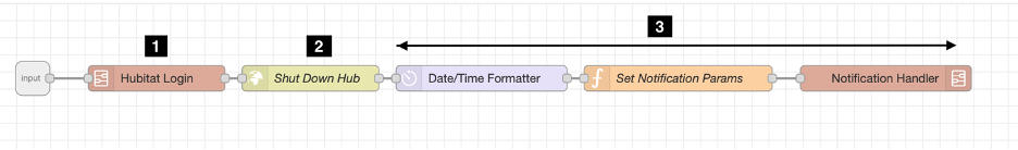
Step 1 : The Hubitat Login subflow is used if you have security enabled on the hub. The logic of the subflow is documented in this thread Using Node-RED to log in to Hubitat with security enabled [SOLVED] - #2 by rakeshg

I replaced the “Change” node in the original flow with the node-red-contrib-credentials, but there is no other change.
Step 2 : The validated credentials are used by the http request node to initiate the shut down. The URL is http://YOUR_HUB_IP/hub/shutdown. If your hub does not have security enabled, you can just use this step and discard Step 1.
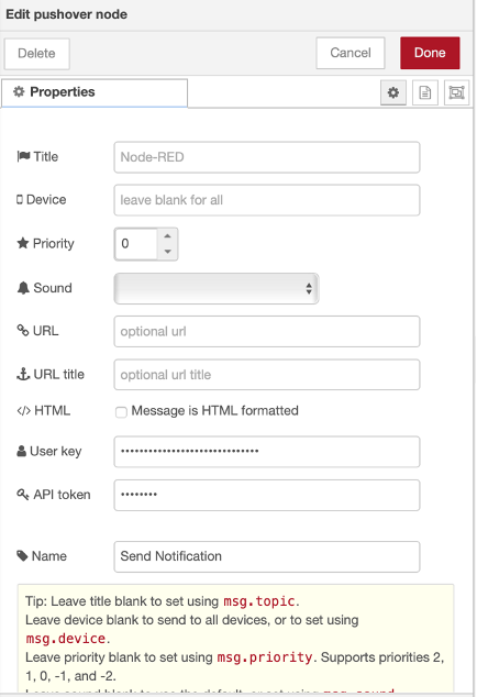
Step 3 : These steps are used multiple times to send Pushover notifications.
The Date/Time Formatter node from node-red-contrib-moment is used for getting the formatted date/time to include in the Pushover message.
The function node formats the message to conform to the Pushover node requirements.
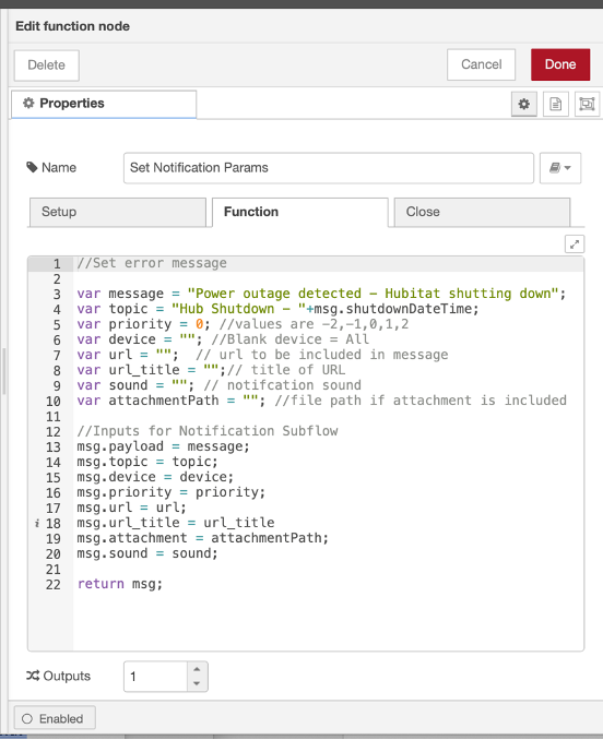
Function Node Code
//Set error message
var message = "Power outage detected - Hubitat shutting down";
var topic = "Hub Shutdown - "+msg.shutdownDateTime;
var priority = 0; //values are -2,-1,0,1,2
var device = ""; //Blank device = All
var url = ""; // url to be included in message
var url_title = "";// title of URL
var sound = ""; // notifcation sound
var attachmentPath = ""; //file path if attachment is included
//Inputs for Notification Subflow
msg.payload = message;
msg.topic = topic;
msg.device = device;
msg.priority = priority;
msg.url = url;
msg.url_title = url_title
msg.attachment = attachmentPath;
msg.sound = sound;
return msg;
The Notification Handler subflow only has the Pushover node configured with the User Key and API Token.
Hubitat Restart Subflow:
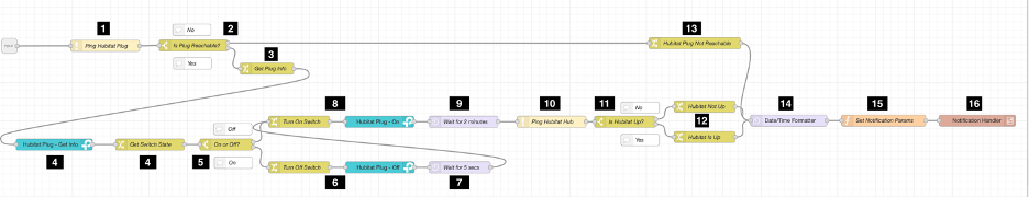
Step 1 and 2 : These are similar to Step 11 and 12 in the main Hubitat Outage Management flow, except the Ping node is configured to ping the Kasa (TP-Link) plug. If the plug does not respond (plug is offline), the flow sends a notification in Step 13, otherwise it goes on to Step 3.
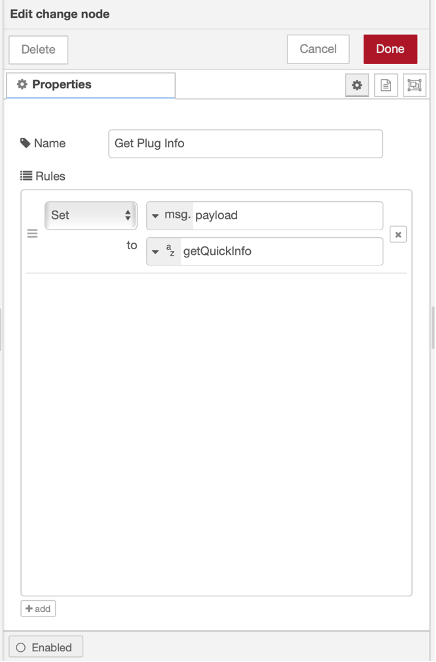
Step 3 : The change node configures the command to request the status of the Kasa (TP-Link) wifi plug
Step 3: Change Node
Step 3: Kasa Node
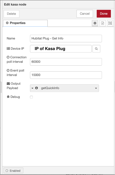
Step 4 and 5 : The getQuickInfo command returns various Kasa plug attributes and the Change node (Step 4), parses out the current state (payload.sysInfo.relay_state = 0 or 1, 0 = Off, 1 = On). The Switch node in Step 5 directs the flow depending on whether the plug is on or off (typically, it will be on and it should return to the state it was in if the when the power is restored and the UPS has run out of battery).
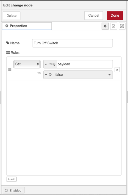
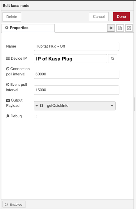
Step 6 : If the Kasa plug is on, then the flow turns if off in order for the hub to restart. The Change node configures the command to turn the plug off.
Step 6: Change Node
Step 6: Kasa Node
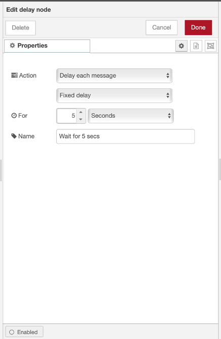
Step 7 : The Delay node is configured to wait for 5 seconds and then proceed.
Step 8 : The configuration of these nodes is very similar to Step 6, except that msg.payload in the Change node is “true”.
Step 9 : The Delay node (similar to Step 7) delays the execution for 2 minutes to give time for the Hubitat hub to reboot (NOTE: This time may need to be adjusted depending on how long your hub takes to reboot).
Step 10 and 11 : These are similar to Step 11 and 12 in the main Hubitat Outage Management.
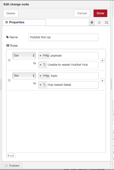
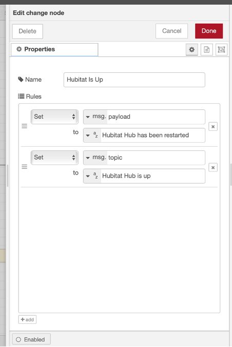
Step 12 : The change node(s) determine the text to be sent in the notification depending on the state of the Hubitat hub
Step 12 Change Node: Hubitat Not Up
Step 12 Change Node: Hubitat Up
Step 13 : If the plug cannot be reached (Step 2 above) the change node creates the message that will be sent with the notification (similar to Step 12)
Step 14, 15, 16 : Same as Step 3 in the Hubitat Shutdown Subflow.

