In another thread, I was informed by one of the experts that current-revision door sensors use hall-effect sensors, which would frustrate kluging them as one could with the older reed-switch sensors to use as, for example, budget puddle detectors.
I saw where someone was steady-handed enough to be able to solder wires to a sensor, so I thought I'd explain how one might get back from a hall-effect sensor to a contact closure. Its not that complicated:
A hall effect sensor is generally going to have an output that is 1/2 the supply voltage when not exposed to a magnet, and higher than 1/2 when it is exposed, with a higher voltage the closer the magnet comes.
So, we can remove the hall effect sensor (or just cut the output lead, and replace it with a simple voltage divider, where a reed switch connects or shorts out a resistor.
Refer to the sketch, excuse my (ancient) shaky hands:
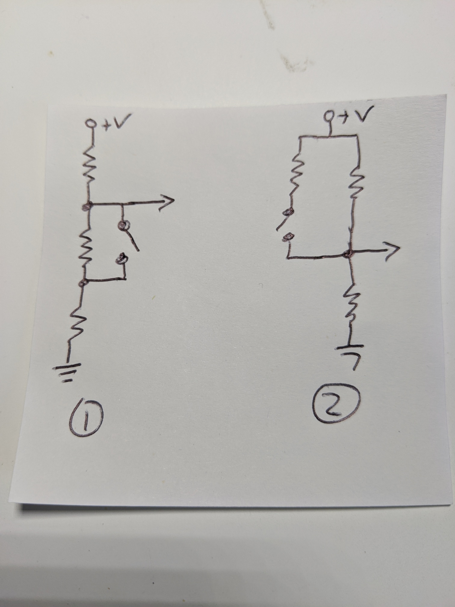
In (1), when the reed switch is open, the output at the arrow is 2 volts, the same output if the hall effect sensor detects a magnet ("door closed"). This is good for a normally-closed reed switch. (This assumes the Iris sensor, which has a 3-volt battery)
In (2), when the reed switch is open, the output at the arrow is 1.5 volts, the same output if the hall effect sensor does NOT detect a magnet ("door open"). This is good for a normally-open reed switch.
If one uses all 100 meg-ohm resistors, you get a very low current:
3V / 300 Meg-Ohm = 10^-9 amps = 10 nano-amps for (1) with the switch open, 15 nano-amps with the switch closed.
In (2) you'd have 15 nano-amps with the switch open, and 20 with it closed. This seems a reasonably small current drain for a battery device.
For those unclear on the "electronics", you add resistors by putting them in series, while in parallel, the net resistance from two identical paralel resistors is one-half their normal value. As voltage drops are proportional, you can "pull up" or "pull down" the voltage to whatever you'd like.
I am assuming that if the hall-effect sensor puts out 1/2 the supply voltage when seeing nothing, then 3/4 the supply voltage is going to be sufficient to "trigger" the detection. I could be wrong, you might need more voltage, maybe 7/8ths the supply voltage, requiring different resistor values.
A Hall-effect sensor should only have 3 leads to it, power, ground, and the output signal. I have a few of the Iris 3320-L door sensors, and I cannot even locate the hall-effect sensor, so I doubt my eyes will let me solder a wire to one of the pads.

