I've installed the IDE, managed to add support for the esp8266, changed the port to Com4 and managed to upload the example 'blink' sketch successfully (it's making the device blink as planned).
Unless I'm missing something, it feels like I need to manually create a tonne of folders and download quite a few items via 'save link as....'. - surely I'm missing something? =p
I have done similar to what you're trying to achieve and linked my existing intruder alarm devices via outputs to inputs on the arduino. It works great and can't thank @ogiewon enough for the time and effort he's put into this.
This may have been mentioned in this post before but i'll just add this anyway.
One thing to note, when you have it lay out on the bench and are testing it, it's great, however when you come to do the installation it becomes a fiddly nightmare...
Let me explain. The Arduino's are nice and small and are easily placed in small boxes, that is until you start wiring them. If like me you're using relays to convert the signal from a wet to a dry contact then you need room for them too. So now the enclosure just got bigger. Next you need room for the wires to go from device to device, you need enough space to be able to get your ethernet cable in and if you're using it the USB cable. If you then get giddy (like I did) and decide whooaaa you can add allsorts to this for the HE to see (like temperature sensors, luminance sensors, voltage sensors, output relays etc etc) then there's more wires. Then you realise theres only a couple of 0v & 5v sockets so you have to start doubling up on them or placing them into a shared terminal block (which gets very full).
So now your arduino enclosure just got massive and very messy with everything going on inside of it! Slowly becoming a mass of tangled wires
My advice is to plan it out thoroughly first, there are enclosures available to buy that plug on to the boards and will give you screw terminals, consider one of them (shown somewhere in this thread previously). Make sure that wherever you decide the board is going to be installed that there's adequate room for everything you are connecting and make sure it is serviceable in the future. Consider getting some Dupont crimpers & crimps for connecting wires into the board. Also check for your own knowledge how it would react if there was a power failure - is it battery backed, is your HE/network battery backed - would you like to receive a notification of a power failure and is it possible to do so.
Another idea is to take notes/make a drawing of how its wired because i guarantee in three months when you have to check something you won't have a clue.
Finally, when you have it setup how you want it and prove it all works how it is supposed to, make sure you save that sketch somewhere safe. To my (limited) knowledge, If you lose that you're not getting it back and will have to write the whole thing again before you tweak it or reload it.
I am currently working on a project wanting to control a PWM CPU fan through an Arduino Nano 33 IoT and Hubduino. I got this running with the <EX_PWM_Dim.h> library to a certain extent, using a mosfet, and simply not using the built in pwm line of the CPU fan.
Nevertheless to control this fan more accurately it requires a proper PWM signal between 21-28kHz, which the standard Arduino PWM cannot provide (only 0,5-1kHz). Luckily someone already developed a PWM library for SAMD-based Arduinos as the Nano 33 Iot to increase the PWM frequency up to ~90kHz (GitHub - ocrdu/Arduino_SAMD21_turbo_PWM: Fast-PWM library for SAMD21-based Arduinos (so far: the Nano 33 IoT (tested), the Zero (untested), and the MKR series (untested))). This library is working fine running some simple and local (non-hubduino) test sketches on the Nano 33 IoT.
Now the big question is how to implement the "Arduino_SAMD21_turbo_PWM" library into the Hubduino sketch?
I understand the regular analogWrite() function is used in the "EX_PWM_Dim.cpp" to determine the regular PWM signal within the "m_nCurrentLevel" variable.
Similarly the "Arduino_SAMD21_turbo_PWM" library provides a "pwm.analogWrite([pin number], [duty cycle]) function. The "duty cycle" being the same as the "m_nCurrentLevel" variable. This is typically used in the .ino sketch.
I haven't yet completely understood how .ino sketches and libraries interact with each other. But I'd like to know if I can refer to the m_nCurrentLevel variable within the .ino sketch, so I could use it as an input for the "pwm.analogWrite([pin number], [m_nCurrentLevel])"? Or is there another way to implement the "Arduino_SAMD21_turbo_PWM" library?
Please let me know if you need more information from my side!
Had a chuckle as I read this, literally every sentence resonates with where i'm going with this ..
Loads of unnecessary additional sensors just because i can? CHECK!
Researching breakout boards for screw terminals? CHECK!
Need an enclosure the size of a gas meter box? CHECK!
Need a diagram on the back of the enclosure box lid? CHECK!
Seriously though, all noted and it confirms most of the things I was thinking about. I know who to ask now when it hits the wall
Not easily, nor is ST_Anything designed to do this.
Yes, the proper way would be to use the "EX_PWM_DIM.h" and "EX_PWM_DIM.cpp" as a baseline to create a new device class, named something like "EX_TURBO_PWM_DIM.h" and "EX_TURBO_PWM_DIM.cpp".
Are you a C++ developer? If so, this should be relatively simple for you. If not...well it'll be slightly more challenging.
dev:5172021-05-11 17:11:31.663 errorChild device creation failed. Please make sure that the 'null' is installed and published.
dev:5172021-05-11 17:11:31.658 errorChild device creation failed with error = com.hubitat.app.exception.UnknownDeviceTypeException: Device type 'Child Contact Sensor' in namespace 'ogiewon' not found
I had a question, but @joldrackhas kind of asked the same thing. I was looking to report some values from the DHT temp/humidity sensor into HE and also to the arduino board to use on a LCD out - i get that it can't be done and was never the intention of HubDuino.
If i include the DHT.h library explicitly within my sketch, and jump/split the data output pin of the DHT to a second pin on the board, would this cause a problem? I see that DHT.h is included in the PS_TemperatureHumidity.h file, so will there be a conflict there.
Finally if so, can it be so simple as to make a 'DHT2.h' driver by copying and renaming and implement that with the jumped pin method?!
I imagine it is obvious but in case not i am definitely not a C++ developer
It can easily be done, but you'll need to write a little bit of code within the sketch to do so.
Every example sketch in my GitHub repo includes a 'callback()' function. I recommend you uncomment the code as shown below and then watch the data that is being transmitted to Hubitat in the Arduino IDE's Serial Monitor window to get a feel for the data formatting. Once you understand it, parse it as you see fit and update your LCD screen.
//******************************************************************************************
//st::Everything::callOnMsgSend() optional callback routine.  This is a sniffer to monitor
//    data being sent to the hub.  This allows a user to act on data changes locally within the
//    Arduino sktech.
//******************************************************************************************
void callback(const String &msg)
{
  Serial.print(F("ST_Anything Callback: Sniffed data = "));
  Serial.println(msg);

  //TODO:  Add local logic here to take action when a device's value/state is changed

  //TODO:  *** Add code here to update your LCD screen with the information parsed from the 'msg' String variable. ***

}
Ah I remember seeing this now in the sketch - clearly I didn't understand what it was telling me properly. I will take a look at this as things progress, at the moment it is enough to know that it can be done and this is the method. Thanks again @ogiewon.
Has anyone been successful with Sonoff Basic R2 devices?
I just used my last 'non-R2' devices (they work great, BTW) and was about to order a few more but see that only R2 units are available.
'thought I'd check before I place the order.
Ok - i have inputs for motion/contact working. Looking at getting some temp/humidity from the DHT11 and i am having a problem (using the W5x00 multiples sketch, and i haven't touched the callback yet). If i run a basic DTH sketch on the arduino i can get the sensor reporting in the serial monitor so i know that it is good.
In hubitat on both the temp and humidity child pages, I am getting a value of -1 on both. So, allowing that i have the data pin right (leap of faith i know), where to start?
I have had another look and am still hitting the wall. I've tried 2 sketches which can be downloaded at the link - can't figure out how to upload code here! I did check the FAQ's etc but couldnt see it. Valid for a week, if it expires just shout and I will redo. The basic DHT11 sketch seems ok, but the Multiples sketch is giving me trouble.
The first trial is the standard Arduino DHT11 sketch, works ok as you can see in the clip below. The physical setup is shown in the pic.
I have been using the standard Multiples sketch, modified only for my IP details etc and with the callback commented back in. The only change to the physical setup is the addition of a jumper wire to pin 26 so i can ground it out and test the contact 1 sensor. All devices are created correctly, contact 1 is working when i ground the wire(ie 'current state' flips open/closed as i place/remove the wire), but nothing from the DHT11 sensor. The serial monitor is reading nonsense to my eyes but perhaps to someone who can read 'the matrix' it will mean something.
Let me know if any more info from me would be useful.
Assuming you are using one of the fairly large ST_Anything_Multiples sketches designed for the Arduino MEGA, have you changed the example device declarations from using DHT22 sensors to using DHT11 sensors?
No, I didn’t. I read the code and thought I had picked up all the changes. I imagine that will sort it seeing as everything else seems ok. Will try over the next day or two and confirm.
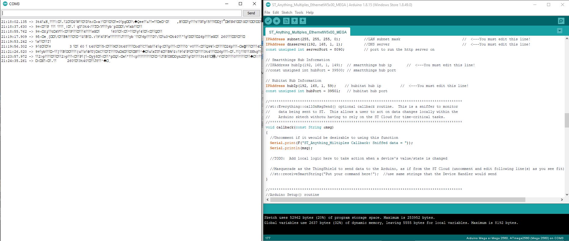
That has corrected the communication with HE and the temp/humidity data is coming through. I am still getting odd info coming through on the serial monitor though. I have included in the screen grab below the section where i have uncommented the callback function in case I have done something wrong there perhaps?


 ..
..
 can any help me please