That is an interesting concept! A capacitive touch interface mounted underneath your existing kitchen countertop. Very interesting, indeed.
I would have to understand the CapSense library much better before knowing whether or not it would interfere with the network communiciations used by the HubDuino libraries. I just don't have much time right now to investigate this.
If you're a C/C++ programmer, I would encourage you to take a look at the IS_Button.cpp and IS_Button.h files within the ST_Anything library to see if you could use them as a starting point for incorporating the CapSense library (versus the simple pushbutton design using simple digital inputs.)
From the Hubitat side, we'd want the CapSense devices to look like any other Button Controller, with PUSHED and HELD events based on how long the user leaves their hand on the sensor.
i'm not using an arduino for that, but am using a ZEN16 for it and a physical button. i have a virtual switch that will determine if the physical button will function or not (trigger a device connected to it)
Thank you!
I also hope to be able to make it working.
The CapSense library is really simple to use: you build an object that reference two pins; you set some values, depending on the capacitance and the responsiveness; you ask the library if at that moment there's a touch.
I'll dig into your code. But now it's clear that I can't just add is as a library and use it: it should be adapted to the way I use the arduino board. But, it looks also that is something possible.
Now I think I've got what you mean. You speak about the "wake up" button, right? Sorry... It was really an unhappy selection of words.
The activation/deactivation is something that stays inside the arduino program. If you see the video of the hardware I've linked it should be clear what I mean.
I just want to have this because I don't want to fire any command whenever I touch the surface. I want to activate the device (the sensing, actually) and the i send a command touching any other button.
Just to let you know that ive managed to connect my Arduino curtain project to HE by using the FauxmoESP library Alexa and virtual switches, it all works very well and even the on the Alexa side the cloud is somehow bypassed and so i get voice control without internet.
So, I've had a really deep look at the various boards/ICs/etc that add to Arduino capacitive sensing. I've found that I can use the Adafruit mpr121. I've to play a bit around to correctly configure everything, but it looks much more more reliable and less error prone then building my own buttons.
If I manage to have everything working, I've the problem that the communication is over I2C. Using a custom library I can configure the IC and receive a "simple to handle" response from it. But, this means that I don't use any pin of the Arduino.
So, with this premises:
extra hardware attached to Arduino
no pins, but I2C connection
simple to handle response from IC
which would be the best piece of code to see/check/analysis/modify (at the end) for managing all this? I've had a look at the GitHub repository, but I can't find the files you've suggested (IS_Button.*).
Anyway, I suppose that I've to:
write a custom library (something like here - I this I've to extend this class st::Executor), to manage the hardware that I use, in this case the Adafruit board
in my sketch I use it as a simple configurable sensor.
(optional, but nice to have to avoid really long debug - watching seria output - sessions: some tests to check if all it works as expected)
Am I right?
If yes, I'll need months to do everything. I program, but with Java. With Arduino I can do some things, but nothing so complicated. It will turn out into a really big challenge.
Extra question: have you ever tried Platformio? When I program a board, I use Visual Studio with it, it's much simpler to manage the code compared to ArduinoIDE.
Here is a link to the IS_Button.cpp file I mentioned earlier.
I2C does utilize 2 pins on the microcontroller. There are several examples within the ST_Anything Arduino Libraries where I have added support for specific I2C sensors. Most all of these are sensors that are polled every 10+ seconds for things like temperature, humidity, illuminance, etc... I have not tried adding anything like the MPR121 capacitive touch sensor, which would need to be communicated with much quicker, however it seems like it would be fairly trivial to add support for it based on the example Adafruit sketch.
If Arduino C++ programming is not a strength of yours currently, it may be a little challenging. I would still start with the IS_Button code as a starting point, though...
This would not be an an Executor class... It would be an Interrupt Sensor (don't get hung up on the name 'interrupt', as devices of this class type are simply called every pass through the Arduino loop() routine.)
Correct, once a new "IS_Button_MPR121" class is created, it can simply be added to sketch like any other ST_Anything device.
It is very easy to output data to the Arduino IDE's Serial Monitor window, as long as the microcontroller is connected via USB to the computer.
Now I've some basics to work with. I've just to deep dive into the code and get back from my memories that bit of c++ I've learnt years ago. But, at least it looks that the thinks are possible. So I'll try.
I ordered a MPR121 board as I am curious about this technology. Once it arrives, I will try integrating it with HubDuino/ST_Anything. Looks interesting! I'll let you know how it goes.
... Because I'd like to hook them up to one of my many (!) unused esp8266 and create a DIY lux sensor.
I've intended to take a crack at this excellent piece of software of yours for quite some time, but so far my usage has been fairly off-the-shelf and konnected has covered the bases.
I haven't a shred of arduino experience at all, and generally my time is limited/interrupted by small humans living rent free in my house! =p
I've read the readme and it looks pretty technical. Do you have any hints on where someone in my position may be able to start, to accomplish a simple project like this, without struggling with a potentially huge learning curve? I'd love to get my feet wet and I can see the possibilities are literally endless, but don't know quite where to start. =)
The first place to start would be just getting the Arduino IDE installed on your computer, and learning how to use the IDE's features. There are lots of online tutorials to help get you started. Be sure to spend some time learning about Arduino "Sletches", "Libraries", and "Boards".
Sketches are the main program that users write within the Arduino IDE.
Libraries are additional code that allow the Arduino IDE to perform additional tasks, including things like talking to your BH1750 illuminance sensors.
Boards are supporting software to allow the Arduino IDE to program and load compiled sketches on to various microcontrollers.
Learning these basics is essential to using the Arduino IDE, and the HubDuino/ST_Anything project assumes the user already knows these basics. I recommend building a basic foundation of knowledge and understanding on core Arduino IDE principles prior to even reading or downloading the ST_Anything project. It will make much more sense after you learn the basics.
HubDuino/ST_Anything is a set of building blocks that the Arduino programmer can use to build "Anything" they'd like, and have it easily integrated with Hubitat. The project consists of two main parts, the HubDuino Hubitat Groovy Drivers and the ST_Anything Arduino Libraries. Together, these two components are what allows an Arduino Sketch to be easily written to tie real-world physical devices (e.g. your BH1750 sensors) to a Hubitat hub. I have provided some example sketches to demonstrate how these pieces all fit together. The one of most interest to you would probably be the following. It has example device definitions for many different I2C sensors, including a commented out line of code for the BH1750 sensor. When you get to this point, let me know and I can assist you with a custom sketch specific for your needs if you require assistance.
I have a question! I think it is more of an Arduino question than a Hubduino, but the lines are a bit blurred for us beginners.
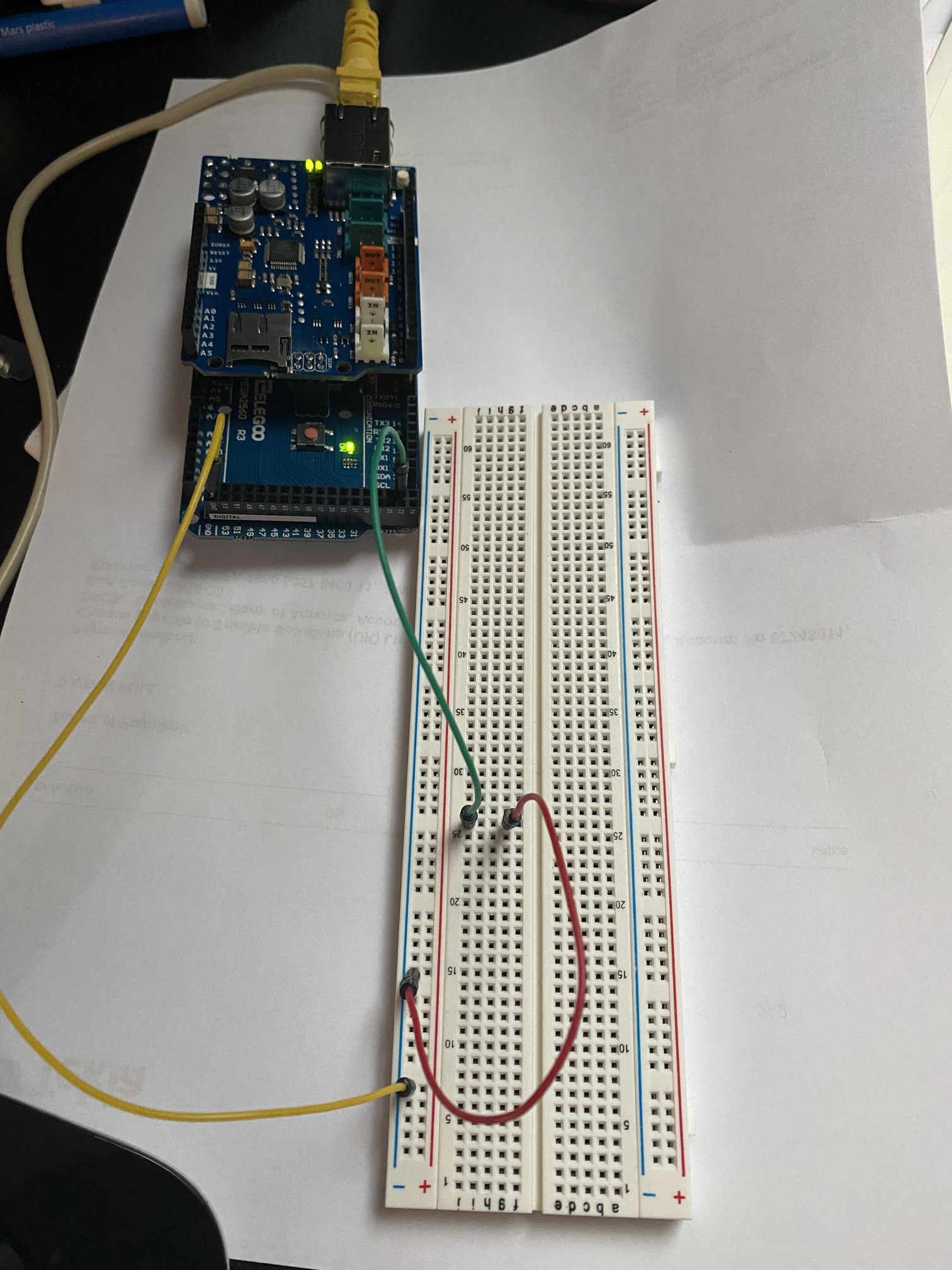
After a bit of studying i have got Hubduino talking to HE, and have rigged up a little test using the ST_Anything_AlarmPanel_Ethernet5100 sketch (which i modified slightly to use the 5x00 library). All well and good and all working. My end goal for this is to run a few sensors (temp/humidity) but mainly to bring in my alarm sensors. These will be taken off the alarm panel board as outputs programed to mimic each sensor, so its simply 12v on or off out of the panel output depending on the state (and the panel output can be inverted if necessary).
Lets put aside the 12v issue for the moment - i know i need to do something to drop this down. The image below shows my trial rig - pulling and replacing the red jumper causes the sensor to change state so all is working. What i'm confused about then, is that the board is putting out some voltage through the pin, and when i ground it thats what changes the state. I expected it to be at 0v and to be looking for voltage 'in'.
Maybe that last statement has given away my lack of electronics knowledge, but i was expecting to have an input watching for a rise in voltage, Any pointers would be great.
This is an excellent question, that is not usually very obvious to new users of Arduino-style microcontrollers. By default, I have configured all of the example sketches to utilize a feature supported by most microcontroller board's digital inputs called a "INPUT PULLUP RESISTOR". This feature causes the digital input pin to put 5v (or 3.3v depending on the board) on the digital input pin. Thus, the PIN is in a HIGH state electrically until the something, like a contact sensor's switch, drops the voltage down to 0v (or GND).
Wiring Contact Sensors in this way has the advantage of always triggering the input even if the wires are cut. The only way for the input to go low is if the contact sensor's switch connects it to ground.
Another important concept to understand is that a digital input can actually have three different states:
High - 5v is present on the input
Low - 0v is present on the input
Floating - this is bad, as the input may be interpreted as either high or low.
It is important to never let an input 'float', if you want to be sure of knowing whether it is high or low. Using the Internal PullUp feature helps to ensure that this is the case, and greatly simplifies wiring.
It is possible to disable the Internal Pullup feature (it's a parameter in the IS_Contact device constructor's list of options). If this is done, then one has to either use EXTERNAL PULLUP or PULLDOWN resistors, if the device that the input is wired to does not explicitly send a 0v AND 5v signal.
Perform a Google Search on Internal and External Pull Up/Down resistors and you'll get a much better understanding of what I am talking about.
Personally, I would use some 12v relays that are triggered by your existing Alarm Panel's 12v outputs. Then wire the relay's dry contacts into the Arduino's GND and GPIO pin. The relay essentially is just a 'switch', like the mechanical reed switch door/window sensors.
@ogiewon thank you - that was well explained. 'Motion' type sensor is next and I see that this is set up differently - 'high&false' against the motions 'low&true). I understand what you are saying but will go away and read up, see if I can figure out the implications for me when i use motion before i inevitably have to come back and ask!
About the relays, again i get the principle. I have 16 channels to bring in, i was thinking of one of these types of relay board at the link below, 16 channel 12v option - that looks to me like it would fit the bill being a 12v/5v combo. Have i read the intention right (i sort-of understand relays from having messed with cars). I guess for practicality i will need some kind of common ground rail?
EDIT - answering my own question in a way - to me they might be different inputs (motion, contacts, armed/disarmed etc), but if I use relays then to the arduino its all simple switches: 12v on or off in the same manner. So, best thing for me to do is use 16x contact sensors? Would this would have any implication in HE in terms of usage? For example, if i used it to convey that the alarm had been triggered, am i locked into it being a door contact?
Alarm system is standalone by the way and will continue to do its own thing, i am just looking for some reporting!
Double Edit - would probably make more sense, and avoide confusion, if i use the right sensors at least for motion and contact. I just need to modify those initial states in the motion setup to match the contact. My head is spinning, time for bed!
Having had a read again with a fresh head, I need a 12v relay right? Because my control is the alarm panel at 12v, and as long my switched side (ie Arduino 5v) is less than the relays max rating (dc30v) then I am golden.