I have read this thread up and down, do you have the info on your HVAC monitoring board? I'm looking to do something similar, and hopefully find some sensors to monitor line pressure also.
What would you like to know? I don't have a detailed wiring diagram, at least none that I can find...
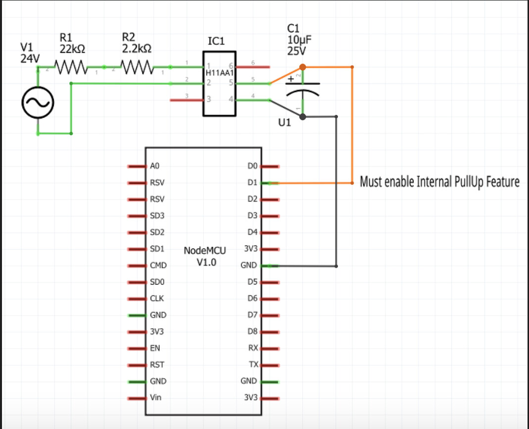
I basically used a piece of protoboard, soldered in a pair of headers that the NodeMCU ESP8266 plugs into. I then added some screw terminals for power, as well as for the 4 DS18B20 temperature sensors, and for the 4 HVAC thermostat signals. Finally, I added a female header to plug in an AM2320 I2C Temp/Humid sensor.
The hardest part was figuring out how to convert the 24VAC thermostat signals into digital inputs on the ESP8266. These components are all soldered to the protoboard as well.
I am trying to find a photo of it all assembled. If I do, I'll update this post.
Just installed second servo for the arduino and now it controls both of them just like that. Really cool!
One thing that made..and still make me feel stupid is powering that arduino and those two servos.
I have usb outlets capable of providing 2.4ah per port (two ports per outlet). I have been using these same outlets since beginning. One port is for the arduino and second for the servo.
Now that I installed second servo, connected it to arduino's pin and then powered it by using one 2.4ah usb port from exactly same kind of outlet that I have been using with all my blinds-> second servo was not powered at all.
This is so weird that I'm trying to explain it to you:
One arduino and one servo
Outlet 1:
usb port 1: arduino
usb port 2: servo nr1
= works
One arduino and two servos (connected to right pins)
Outlet 1:
usb port 1: arduino
usb port 2: servo nr1
= works
Outlet 2:
usb port 1: servo nr2
usb port 2: empty
= not working
Outlet 1:
usb port 1: servo nr1
usb port 2: servo nr2
= works
Outlet 2:
usb port 1: arduino
usb port 2: empty
= works
So it seems like if Arduino is controlling two servos, then Arduino needs to be in its own usb outlet and servos will only work if they are behind same usb outlet. That just does not make sense for me because there is clearly enough amperes to control arduino and servos. And with just one servo both servo and Arduino can be connected to same outlet. I was already thinking that I have wiring problems and I was ready to cut wires and do all wiring again. Just for laughs tested to change arduino behind other outlet and voila..
Yesterday continued installing more servos for my blinds. This is as weird as it was before. For some reason two of my 4 installed windows are acting weird those other two works perfect. Same symptoms as I wrote earlier and I do not still understand how power can cause that kind of weirdness for arduinos and servos.
I need to add arduino to different outlet alone and connect two servos to same usb outlet to get those blinds work. It just does not make any sense. If I'm mixing them by connecting arduino to same outlet as servo and leaving one servo to different outlet...not working at all.
Now that two servos are connected to one outlet and arduino is connected to other outlet, everything works but servos are making small adjustments all the time.
It feels like this is power related but can't just figure it out.
Sorry for the delay in the response. I just now saw your post from a week ago.
When you're using multiple power supplies to control devices connected to the same microcontroller, you typically have to tie the GROUND of each power supply together, so that everything references the same ground voltage potential.
It would really help if you could provide a wiring diagram of each of your configurations, as it is very challenging to try and visualize exactly how you have things wired.
1 Like

Most likely, if both USB ports are from the same power supply in "Outlet 1", the two black from that power supply are already connected to each other internally.
So, try simply connecting the black (gnd) from the Outlet2/Arduino, to the black (gnd) of Outlet1/Servo1/Server2.
Do not connect the red (+5v) wires together from Outlet1 and Outlet2, as that will cause issues.
Set the "detachAfterMove" parameter to True to prevent the servo "small adjustments all the time"
//******************************************************************************************
//  File: EX_Servo.cpp
//  Authors: Dan G Ogorchock
//
//  Summary:  EX_Servo is a class which implements the SmartThings/Hubitat "Switch Level" device capability.
//			  It inherits from the st::Executor class.
//
//			  Create an instance of this class in your sketch's global variable section
//			  For Example:  st::EX_Servo executor1(F("servo1"), PIN_SERVO, 90, true, 1000, 0, 180, 2000, 544, 2400);
//
//			  st::EX_Servo() constructor requires the following arguments
//				- String &name - REQUIRED - the name of the object - must match the Groovy ST_Anything DeviceType tile name
//				- byte pin_pwm - REQUIRED - the Arduino Pin to be used as a pwm output
//				- int startingAngle - OPTIONAL - the value desired for the initial angle of the servo motor (0 to 180, defaults to 90)
//              - bool detachAfterMove - OPTIONAL - determines if servo motor is powered down after move (defaults to false)
//              - int servoDetachTime - OPTIONAL - determines how long after the servo is moved that the servo is powered down if detachAfterMove is true (defaults to 1000ms)
//				- int minLevelAngle - OPTIONAL - servo angle in degrees to map to level 0 (defaults to 0 degrees)
//				- int maxLevelAngle - OPTIONAL - servo angle in degrees to map to level 100 (defaults to 180 degrees)
//              - int servoRate - OPTIONAL - initial servo rate in ms/degree (defaults to 2000, used to ensure a gentle move during startup, afterwards comes from SmartThings/Hubitat with each move request)
//              - int minPulseWidth - OPTIONAL - minimum pulse width in milliseconds, defaults to 544 (see Arduino servo attach() function)
//              - int maxPulseWidth - OPTIONAL - maximum pulse width in milliseconds, defaults to 2400 (see Arduino servo attach() function)
So do I get this right. If grounds are not connected then difference in gound voltage potential causes servos to adjust their position. To fix this issue:
A. grounds have to be connected
OR
B. detachaftermove has to be "true"
OR
C. both for some reason?
I did some testing and found out that if servos are in different outlet and arduino is in different outlet everything works. As soon as there is certain type of electric device connected to outlet 1 or outlet 2 servos starts to adjust their position. Noticed that normal phone with charger connected to outlet causes no problems. Then connected plasma ball to outlet 1 and servos went crazy. Same things happen with outlet 2.
If I get this right..all interference provided from different electric devices (connected to same outlet as arduino or servos) does not matter anymore if either fix A or B are made.. or both.. 
I would do C, personally. The voltage being sent from the Arduino to the Servo is a high frequency PWM signal. The servo must have the same gnd reference as the Arduino. Sometimes the 'ground' wires are called 'common', as they all need to refer to the same potential. Without the ground signal from the Arduino, the pwm signal is considered 'floating' and really has no use.
The detachAfterMove parameter will make the Arduino stop sending the PWM signal after the motion is complete. Otherwise, if the servo detects it is not at the commanded position, it will try to correct itself. This results in the servos buzzing if they can't stay at the exact commanded position.
Hi all.
OK so i have all of the engineering side sorted out and it works. but the Arduino side of things is quite frankly beyond me.... and i need some help.
i have a working basic arduino sketch that is working with Blynk but as soon as i try to add limit switches, it all goes pear shaped, its something to do with the way the loop is formatted.
But then i had a thought, (it didnt hurt much) " what if i learn how to write the sketch for blynk and thats not what i need for Hubitat arduino???" ill have wasted much time and effort....
The aim is to get this working with Hubitat and dashboard/alexa can some one please point me in the direction i need to go to get this working? is it even going to be possible?
The code i have below works with blynk but as soon as i add limit switches it wont work and ive got to re write it.
  Download latest Blynk library here:
    https://github.com/blynkkk/blynk-library/releases/latest

  Blynk is a platform with iOS and Android apps to control
  Arduino, Raspberry Pi and the likes over the Internet.
  You can easily build graphic interfaces for all your
  projects by simply dragging and dropping widgets.

    Downloads, docs, tutorials: http://www.blynk.cc
    Sketch generator:           http://examples.blynk.cc
    Blynk community:            http://community.blynk.cc
    Follow us:                  http://www.fb.com/blynkapp
                                http://twitter.com/blynk_app

  Blynk library is licensed under MIT license
  This example code is in public domain.

 *************************************************************
  This example runs directly on ESP8266 chip.

  Note: This requires ESP8266 support package:
    https://github.com/esp8266/Arduino

  Please be sure to select the right ESP8266 module
  in the Tools -> Board menu!

  Change WiFi ssid, pass, and Blynk auth token to run :)
  Feel free to apply it to any other example. It's simple!
 *************************************************************/

/* Comment this out to disable prints and save space */
#define BLYNK_PRINT Serial


#include <ESP8266WiFi.h>
#include <BlynkSimpleEsp8266.h>

// You should get Auth Token in the Blynk App.
// Go to the Project Settings (nut icon).
char auth[] = "";

// Your WiFi credentials.
// Set password to "" for open networks.
char ssid[] = "";
char pass[] = "";

byte limitCW = D0;
byte limitCCW = D1;
byte directionPin = D2;
byte stepPin = D3;
byte buttonOnOffpin = D4;
byte buttonCWpin = D5;
byte buttonCCWpin = D6;
byte buttonJogCWpin = D7;
byte buttonJogCCWpin = D8;

boolean buttonCWpressed = false;
boolean buttonCCWpressed = false;
boolean buttonJogCWpressed = false;
boolean buttonJogCCWpressed = false;
boolean buttonOnOffpressed = false;


unsigned long curMillis;
unsigned long prevStepMillis = 0;
unsigned long millisBetweenSteps = 1; // milliseconds

void setup()
{
  // Debug console
  Serial.begin(9600);
  Serial.println("Starting Stepper Demo with millis()");

  pinMode(directionPin, OUTPUT);
  pinMode(stepPin, OUTPUT);
  pinMode(buttonOnOffpin, OUTPUT);

  pinMode(limitCW, INPUT);
  pinMode(limitCCW, INPUT);
  pinMode(buttonCWpin, INPUT);
  pinMode(buttonCCWpin, INPUT);
  pinMode(buttonJogCWpin, INPUT);
  pinMode(buttonJogCCWpin, INPUT);

  Blynk.begin(auth, ssid, pass);
}

void loop()
{
  Blynk.run();

  curMillis = millis();
  readButtons();
  actOnButtons();

}

void readButtons() {

  buttonCCWpressed = false;
  buttonCWpressed = false;
  buttonJogCCWpressed = false;
  buttonJogCWpressed = false;
  buttonOnOffpressed = false;

  if (digitalRead(buttonCWpin) == HIGH) {
    buttonCWpressed = true;
  }
  if (digitalRead(buttonCCWpin) == HIGH) {
    buttonCCWpressed = true;
  }
  if (digitalRead(buttonJogCWpin) == HIGH) {
    buttonCWpressed = true;
  }
  if (digitalRead(buttonJogCCWpin) == HIGH) {
    buttonCCWpressed = true;
  }
  if (digitalRead(buttonOnOffpin) == HIGH) {
    buttonOnOffpressed = true;
  }
}

void actOnButtons() {
  if (buttonCWpressed == true) {
    //while (limitCW = HIGH)
    digitalWrite(directionPin, LOW);
    singleStep();
  }
  if (buttonCCWpressed == true) {
    digitalWrite(directionPin, HIGH);
    singleStep();
  }
  if (buttonJogCWpressed == true) {
    digitalWrite(directionPin, LOW);
    singleStep();
  }
  if (buttonJogCCWpressed == true) {
    digitalWrite(directionPin, HIGH);
    singleStep();
  }
  if (buttonOnOffpressed == true) {
  digitalWrite(buttonOnOffpin, HIGH);
  }
}

void singleStep() {
  if (curMillis - prevStepMillis >= millisBetweenSteps) {
    // next 2 lines changed 28 Nov 2018
    //prevStepMillis += millisBetweenSteps;
    prevStepMillis = curMillis;
    digitalWrite(stepPin, HIGH);
    digitalWrite(stepPin, LOW);
  }
}```I have never used the Blynk library, and thus I am not sure if/how one would go about integrating it with Hubitat. This is not something that I personally have the time to dig into to try to understand.
As I have mentioned multiple times over the years, robust, reliable stepper motor control is much more complex than most folks think at first. For me, trying to add that functionality to HubDuino, would be a lot of work as it would require trying to cover every end-user's specific use-case. Since each of these use-cases is pretty unique and niche, I fear no one would be fully satisfied with a base level of capability. Thus, I have always encouraged users to get things working as a standalone sketch and then attempt to integrate it with Hubitat. The problem with this approach, is when something like Blynk is added to the mix which in many ways is probably attempting to do the same things as HubDuino. This will lead to conflict as to who is really in control of the network communications... 
Hi Dan.
actually it is working as a stand alone sketch and only got complicated when i started to use blynk, which is why i asked the question before i invested lots of time trying to get it to work with blynk properly.
To all intents and purposes my stepper is acting as a simple motor with limit switches.
What im asking you is how to configure the sketch so that i can use your app to make it work?
so if i get the sketch to work with push buttons we can then get it to work with your app? all i need to do is add in limit switches and with blynk thats where it got complicated and virtual pins were required.
if you look at the sketch it is just a basic on off type affair.
Ok, I see that now. I thought your sketch was somehow dependent on Blynk, which I am pretty sure would be an issue.
So, your sketch is very simple, as you mentioned. How exactly would you like the Hubitat integration to function? This is where things start getting interesting, IMHO. What you have currently is a manual stepper motor controller, based on a user pushing manual buttons, and releasing as they watch what is happening in the physical world. Thus, all of the timing is being handled by the human brain, not the microcontroller, correct? Thus, there is still much logic to be added to sketch (including the handling of the overtravel limit switches...
Explain how you would like the Hubitat to Arduino interface to work, and I'll try to assist. The most simple integration that I can think of is a simple two-state device. The curtains are either open or closed. Hubitat would simply send to the Arduino a command to either 'open' or 'close' the curtains. Then the sketch takes over and turns the stepper motor until either the open limit switch is hit, or the closed limit switch is hit respectively. At that time, the Arduino would then send back to hubitat the status update of either 'open' or 'closed'
This is similar to how a garage door is handled.
Where it gets much more complex is when you want to be able to open something partially. In that scenario, you need to know how many 'steps' are required from fully open to fully closed. It also requires proper homing of the motion system each time the power is restored so the Arduino sketch has a reference point of where the curtains currently are.
This is the complexity of stepper-based motion control that I mentioned earlier... ![]()
Im just editing the sketch now.
in a perfect world, this is what i want to do:
1: Open curtains button on dashboard: push it once and the curtain motor runs until it hits the limit switch. I was thinking fo using a while condition something like:
 if (buttonCWpressed == true) {
     while (limitCW = HIGH)
    digitalWrite(directionPin, LOW);
    singleStep();
But i understand this is not a good idea?
the same for close curtains.
Then in an ideal world a momentary button on the dashboard that will only move the curtains whilst held down, subject to the limit condition. i was going to use something like:
 if ((buttonJogCCWpressed == true) && (limitCCW == HIGH)) {
    digitalWrite(directionPin, HIGH);
    singleStep();
im a complete novice when it comes to arduino its taken days of pain just to get this far...
@markvk42 - I recall that I previously had created a very basic shell of a sketch for another user who was trying build his own method of controlling HVAC vents. When you think about it, they are either open, closed, or somewhere in between. Thus, I tried to keep it simple by emulating those functions using a Dimmer Switch device. It can be on or off, and have a level. See the parallels?
The following sketch only implements my 'SmartThings..." communications library, which is what HubDuino/ST_Anything uses to communicate to the ST or Hubitat hub. The nice thing about this, is that it is much simpler to see what is going on, and provide much more flexibility for a user like yourself who is trying to 'fill in the blanks' with your own functionality. As an Arduino novice, you've got some work to do to make sure things are well behaved. You must avoid tight loops and delay() statements to make sure the WiFi communications are always being serviced properly.
Take a look at the following sketch, and give it a try. It should work fin using the HubDuino Parent/Child drivers on the Hubitat hub. It will create a single 'dimmerSwitch' child device, which you can use to send 'on', 'off', and 'level' commands to the Arduino Sketch with. Likewise, it sends updates back to the Hub to make sure Hubitat is kept up to date.
There are sections of code marked TODO in the 'on()', 'off()', and 'setLevel()' functions. This is where you would need to handle the commands and somehow move the motor accordingly.
//*****************************************************************************
///   Arduino Hubitat Ethernet ESP8266 WiFi On/Off/Dim Example
///
///   Created by Dan Ogorchock on 2021-03-20
///
///   Notes: The NodeMCU ESP communicates via WiFi to your home network router,
///          then to the ST Hub, and eventually to the ST cloud servers.
///
///   This sketch is very simple and implements the Hubitat "Switch" and "Switch Level"
///   Capabilities.  How these are used if left up to the user.
///
///
//*****************************************************************************

#include <SmartThingsESP8266WiFi.h>

//*****************************************************************************
// Pin Definitions    | | | | | | | | | | | | | | | | | | | | | | | | | | | | |
//                    V V V V V V V V V V V V V V V V V V V V V V V V V V V V V
//*****************************************************************************
//******************************************************************************************
//NodeMCU ESP8266 Pin Definitions (makes it much easier as these match the board markings)
//  DO NOT UNCOMMENT, just for reference
//******************************************************************************************
//#define LED_BUILTIN 16
//#define BUILTIN_LED 16
//
//#define D0 16
//#define D1  5
//#define D2  4
//#define D3  0
//#define D4  2
//#define D5 14
//#define D6 12
//#define D7 13
//#define D8 15
//#define D9  3
//#define D10 1


//*****************************************************************************
// Global Variables   | | | | | | | | | | | | | | | | | | | | | | | | | | | | |
//                    V V V V V V V V V V V V V V V V V V V V V V V V V V V V V
//*****************************************************************************
SmartThingsCallout_t messageCallout;    // call out function forward decalaration

//******************************************************************************************
//ESP8266 WiFi Information    CHANGE THIS INFORMATION ACCORDINGLY FOR YOUR NETWORK!
//******************************************************************************************
String str_ssid     = "your_ssid_here";                                    //  <---You must edit this line!
String str_password = "your_wifi_password_here";               //  <---You must edit this line!
IPAddress ip(192, 168, 1, 221);       // Device IP Address      //  <---You must edit this line!
IPAddress gateway(192, 168, 1, 1);    //router gateway         //  <---You must edit this line!
IPAddress subnet(255, 255, 255, 0);   //LAN subnet mask    //  <---You must edit this line!
IPAddress dnsserver(192, 168, 1, 1);  //DNS server              //  <---You must edit this line!
const unsigned int serverPort = 8090; // port to run the http server on

// Hubitat Hub Information
IPAddress hubIp(192, 168, 1, 149);    // Hubitat hub ip     //  <---You must edit this line!
const unsigned int hubPort = 39501;   // Hubitat hub port


//Create a SmartThings Ethernet ESP8266WiFi object
st::SmartThingsESP8266WiFi smartthing(str_ssid, str_password, ip, gateway, subnet, dnsserver, serverPort, hubIp, hubPort, messageCallout);

int switchLevel;        // current switch dim level (usually 0 - 100)
String switchStatus;    // current switch status ("on" or "off")

//*****************************************************************************
// Local Functions  | | | | | | | | | | | | | | | | | | | | | | | | | | | | | |
//                  V V V V V V V V V V V V V V V V V V V V V V V V V V V V V V
//*****************************************************************************
void refresh()
{
  //Update the Hub with current data from the MCU
  String msg = "dimmerSwitch1 " + switchStatus;
  smartthing.send(msg);       // send message to cloud
  Serial.println("sending: " + msg);

  msg = "dimmerSwitch1 " + String(switchLevel);
  smartthing.send(msg);       // send message to cloud
  Serial.println("sending: " + msg);
}

//*****************************************************************************
void on()
{

  //TODO: Fill in whatever user code is required here

  digitalWrite(PIN_LED, LOW);  // turn LED on (THIS LINE IS JUST AN EXAMPLE!)

  switchStatus = "on";
  refresh();  //update ST cloud
}

//*****************************************************************************
void off()
{

  //TODO: Fill in whatever user code is required here

  digitalWrite(PIN_LED, HIGH);   // turn LED off (THIS LINE IS JUST AN EXAMPLE!)

  switchStatus = "off";
  refresh();  //update ST cloud
}

//*****************************************************************************
void setLevel(int level)
{

  //TODO: Fill in whatever user code is required here

  switchLevel = level;
  refresh();  //update ST cloud
}

//*****************************************************************************
void messageCallout(String message)
{
  // if debug is enabled print out the received message

  Serial.print("Received message: '");
  Serial.print(message);
  Serial.println("' ");

  // if message contents equals to 'on' then call on() function
  // else if message contents equals to 'off' then call off() function
  if (message.equals("dimmerSwitch1 on"))
  {
    on();
  }
  else if (message.equals("dimmerSwitch1 off"))
  {
    off();
  }
  else if (message.equals("refresh"))
  {
    refresh();
  }
  else //must be a level command
  {
    String s = message.substring(message.indexOf(' ') + 1);
    s.trim();
    switchLevel = int(s.toInt());
    setLevel(switchLevel);
  }
}


//*****************************************************************************
// API Functions    | | | | | | | | | | | | | | | | | | | | | | | | | | | | | |
//                  V V V V V V V V V V V V V V V V V V V V V V V V V V V V V V
//*****************************************************************************
void setup()
{

  Serial.begin(115200);         // setup serial with a baud rate of 115200
  Serial.println("");
  Serial.println("setup..");    // print out 'setup..' on start

  // setup hardware pins
  pinMode(PIN_LED, OUTPUT);     // define PIN_LED as an output (THIS LINE IS JUST AN EXAMPLE!)

  //Run the SmartThings init() routine to make sure everything is communicating
  smartthing.init();

  //initialize switch level to 0
  switchLevel = 0;

  //synch up the ST cloud intially (set switch to off)
  off();

}

//*****************************************************************************
void loop()
{
  // run smartthing logic
  smartthing.run();
}
1 Like
Fantastic Thanks.
Hi Dan,
Been playing with this and got it all working including the dim, how do i add more child devices?
You want to add additional devices to the custom sketch above?
What type of devices do you want to add? It’s all about the name/value pairs being exchanged between the sketch and the hub. If you’d like another Dimmer Switch child, then simply send the corresponding “dimmerSwitch2 on”, “dimmerSwitch2 off”, ... strings to the hub. The naming is critical.
1 Like
Hi Dan.
Sorry for the delay, ive been trying to get the code working with buttons, but its all new to me. this is what i want to do and how the code will work, ill need 5 buttons to work in your app 1 latched 4 momentary.
- at the startup, the motor will be OFF; to enable the motor, you must press the start/stop button once;
- when you press the CW (open) button, the motor will start rotating CW and will continue even when you release the button;
- same as 2 for the CCW (Close) button
- when you press the Jog CW button, the motor will start rotating CW and will stop when you release the button;
the motor will stop also when the CW limit switch is pressed; - same as 4 for the Jog CCW button
The Jog buttons will take precedence over the CW and CCW buttons: for example, if the motor is running CW because you pressed the CW button, and then you press the CCW Jog button,
the motor will start rotating CCW and will stop when you release the CCW Jog button.
The Start/Stop button will take precedence over any other button, so the motor will stop immediately when you press the button, even if there are other buttons pressed.
In the stop state, the driver will be disabled so the motor will not draw current.

