Thank-you so much for your write-up on the water meter. I followed your picture and schematic and have it working 50%. For me, that is a huge success as I have little experience with electronics or arduino sketches. I don't know if you can help me get it working a 100%, but I thought I would share where I am at.
Built the breadboard and wired up the Hall sensor and taped it to the meter
Modified the sketch on the NodeMCU ESP-12E for a pulse counter and Power meter
Powered the breadboard up from the 5 volt pin on the NodeMCU
Read 1 volt with my multimeter from the Hall sensor's signal lead
The output going to my NodeMCU will jump between just under 2 volts to just under 3 volts depending if the potentiometer is turned to the left or right.
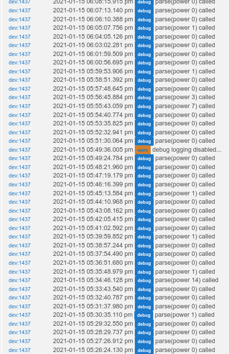
Proceeded to play around with it with no water running. With the potentiometer turned all the way clockwise or all the way counterclockwise, I get the power meter returning 0. It reports about every 1 minute in the logs. With the potentiometer turned to a halfway point the power meter will report very large values of around 2000 every minute. Turned it counter-clockwise till it settled down and was mostly reporting a value of 0 with a rare value of 1 being reported every minute. Turned on my water and I get a value greater than 1, something like 8 or 11. The problem is that although I get a reading well above zero when the water is running, it does not correlate to water usage. Running about a liter of water during the minute returned a value of 14, running about 20 liters of water during another minute returned a value of 7 followed by 3 the next minute.
I bought several other Hall sensors and I think one is more sensitive than the one I am using now, so I could try that. I will also try moving it around on the meter some more to see if there is a better spot (higher or lower on the meter housing). I also have a few buddies looking to see if I can get an oscilloscope to borrow for a weekend.
If you have any other suggestions for how to troubleshoot, it would be appreciated.
Hi before tying into Hubduino.... I had a simple sketch that read pulse count every 1/2 a sec and viewed it on the serial monitor (see below)... using this you can try and place the sensor in the best space. They verify you can turn on a nearby faucet a little and get some count but then the count stops. BTW I can share my updated Child Water if you'd like. Once you get it working, you can enter 2 different meter readings and it will calculate the conversion ratio and output some additional info
I think if you have a different hall sensor with more gain that would be good...as I said the signal is very small. This is a project where a scope comes in very handy. I almost bought one of those mini scopes for under $50 but they realized i had a scope my dad gave me years ago and i miraculously worked.
indent preformatted text by 4 spaces
volatile uint32_t pulseCount = 0;
volatile uint32_t badCount = 0; #define DIGITAL_INPUT_SENSOR D2
unsigned long last_report;
unsigned long current;
sorry I cannot figure out how to put code in that is in a scrollable window
In addition to finding the best spot you will have to adjust the potentiometer...again a scope really helped... I think to prove that this would work I think i used a compass and moved near the water meter and confirmed there was a magnetic field being generated.
Thanks for the suggestion it helped finding the best spot for the hall sensor. The problem I have is if I set the potentiometer in a spot where it reads water consumption. It will never fully go back down to zero {with no water running}. It's like there is background noise which is resulting in some stray pulses. I would like to ask specifically about the 86nf capacitor in your schematic. I ordered one off digikey and since they didn't list much in nf, I converted it {86nf = 0.086u}. The ceramic capacitor they sent was very small, the one in your breadboard picture above looks ten times the size. I wonder if I messed this part up?
Hi, the value I got was from taking a reading with my meter....
I looked with a magnifying glass and there is the markings .1Z
I looked it up...and I think it means .1 uF with the Z being +-20%
So if it was exactly .1uf that would be 100uf (oops I meant to say 100nf) ...since it could be off by 20%
I think the 86nf is correct.
I talked to my Dad for some suggestions...he said it might help to have a 1K resistor and a capacitor in series from between C1 and R1 to ground. I had a few capacitors and I tried that experiment but it didnt seem to do anything.... While I am an electrical engineer, circuits wasn't my strong point. Anyways I looked at the signal coming out of the hall effect and it is REALLY small... like .05 volt swing....which is why the amplifier has so much gain.
Can you tell me what all the hall effect switched you got ? I'd like to see which has the most output per magnetic input. I took some pictures of the scope output and will post shortly
unamplified signal
output after amplifier and schmidtt trigger
Note the pulses stopped after the water stopped although i could get a couple extra. In my Child Water code, I get readings every minute...if the reading was 2 or less, I ignore them.
Hi clever peeps, first of all - Hubduino is awesome so a big thanks to the creators.
I have only just started playing with the Arduino's and have no previous electronics/coding knowledge so I am a complete novice. I have successfully added a few ESP8266's to the Hubitat and they work great for monitoring hard wired door contacts / motion detectors etc
I have had a look through this thread and can't specifically find what I'm personally trying to do so maybe someone can give me some guidance... or tell me it can't be done...
I want to monitor a low voltage (12-16v DC) supply, I want to be able to display the realtime voltage on a dashboard tile and if possible create an alert if the voltage drops below a certain threshold (say 11v but the alerts aren't essential - just a nice to have).
I am using a NodeMCU 12E esp8266, following the instructions I have added it as a device and uploaded the ST_Anything_ESP8266WiFi.ino sketch.
As a test i'm just hooking up the A0 pin to 3.3v and the parent device which I have added and is online, reads the voltage between 0v to 3.3v no problem however i'm not 100% sure what to do next.
I can see there is a 'child voltage' driver available but I haven't a clue as to how to add A0 as a child device and for it to then be a 'dashboardable' device (if that makes sense). When I refresh the parent it sees temperature, humidty sensors as children but nothing child voltage.
Do I need to modify the sketch in any way to accomodate for this (bearing in mind I'm a total noob!)? Or is it not possible? Am I out of my depth and likely to drown in code lol?
@EVOLVING.HOME
if you are using a node mcu the ADC input max is 3.3v
I would recommend creating a voltage divider that when you have 16v, the output is around 2.8v in case your 16v ever goes higher.
I calculated a resistor divider that would have a ratio of 10/55 = .1818 (16v * .1818 = 2.9V)
Then add the PS_Voltage device and fill in all the parameters...there is a raw min and max and then another Engineering min max
I would put 0 and 3.3 for raw and then based on the resistor divider put the eng min max as
0 and (3.3/ratio) for example if you used the one i suggested the value would be 18.15
@dazpad@nclark
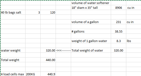
I was able to wire up the 4 load cell setup and load the calibrate code... I had a lot of trouble with the D1mini not coming up...i would power cycle and it would come up and allowed me to calibrate ... I used 2 10# weights and when i took 1 off, it showed 9.88# .....close enough for me in regard to checking water softener.
Q1. Have you guys seen flakiness in coming up ?
Q2. After calibrate and a power cycle what should happen...should it ask to calibrate or just start displaying... i cant tell if my unit is doing what its supposed to since its flakey
Q3.I don't want to buy the voltage converter and wondering if either of you have tried to adapt the code to fit the Hubduino architecture ?
Thanks again for all your help, I have it working about 95% which is good enough for me. I put two 68nf capacitors in parallel for C3, this should give me a capacitance of 136nF or 0.136uF. This seems to be working better.
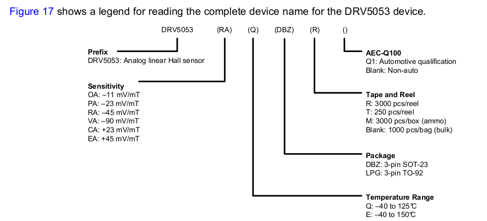
I bought the following Hall sensors from Digikey:
DRV5053VAQLPG
DRV5053RAQLPG
DRV5053EAQLPGM
DRV5053OAQLPG
I am using the DRV5053VAQLPG based on this from the manufacturer:
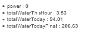
For testing purposes I set the update frequency to 15 seconds. What I notice is that it accurate counts water usage up to about 55 pulses (for 15 seconds). This is for one aerated tap wide open. If a open a second similar tap, the reading will momentarily dip to around 40ish until it goes up to about 90 and then stays there for each subsequent 15 second interval, if I then open up a third tap the next reading will drop down to around 30-40ish, before going up to around 120 for all subsequent readings. Shutting all taps off results in the reading going back down to zero, with a few stray 1 or 2's in the next 5-10 readings and then settling down right at zero.
Anyway, this is plenty good enough for my purposes and I plan to start playing around with the HE side of things. I should be able to determine my accuracy by comparing my HE calculated values with my water meter dial.
Nice choice on the VA version as that is the most sensitive!!
...I don't know why I picked the RA version duh
Anyways if you want my Child code I can post
congrats on the progress !
Tim
This is great advice. I would caution that the RAW values are in units of raw counts for the ADC. So, for an ESP8266, it’s ADC has a 10 bit resolution, or raw values of 0 to 1024.
Hi all, just to confirm that I'm understanding this right. I'm migrating from ST to Hubitat. I have successfully used ST_Anything to control my blinds in ST environment. Now that I' migrating I need to do some things to get my blinds working with Hubitat too.
My sketch says:
"// 2018-02-09 Dan Ogorchock Added support for Hubitat Elevation Hub"
So support for Hubitat is there and I just need to uncomment port-line and set hubitat hub ip address to sketch.
After that I need to install drivers from here:
and follow rest of the instructions to create devices to Hubitat.
Yes, that’s the basic process. In the sketch, simply change the “Hub” IP address to be that of your Hubitat Hub (instead of your ST Hub), and change the port from 39500 to 39501. Rebuild the sketch, and load your microcontroller.
Follow the HubDuino ReadMe to install all of the HubDuino drivers on your Hubitat hub, and then manually add a virtual device, assign it the HubDuino Parent Ethernet driver, and then fill in the IP a address and port (8090) of the microcontroller.
@tim.ocallag, I did not get to trying it out yet since I don't have the parts, but to tell you the truth, I might not be going this route after all, a quick search on my water softener weight and all that goes around it that I would be overloading the scale way to much, since my water softener is a single unit, the machine empty is 120 lbs + 50 lbs of resin beads, then I can put in 200 lbs of salt plus about 50-75 lbs of water just in the brine. Then there is all the water inside the the softening cylinder that I can estimate at about 200 lbs. This makes a total of around 650 lbs. This is already over the critical deformation of the load cells I was going to use.
Getting the bigger load cells makes this a very expensive project that I will not get into right now. So I will most likely just use a waterproof ultrasonic transducer to measure how high the salt is.
Ha, if I wasn't so far along i would do the transducer....but I'm tpo far along : ) (I do have $8 invested for the 4 cells and hx711 board)
Anyways, mine is just a salt tub and so I did some calculations and I'm right on the edge...although
the height of the water is conservative....I think its actually less and plus that height is with salt there so I think its quite a bit less. Here's my calculations
Looks good, I think you should have less water than that but I might be mistaking, this is most likely the max water when doing the brine cycle. So with your calculations, you should always have a reading, that's nice. Good luck and report back, if I change the water softener in the future, I might go that route with a separate salt tank.
The transducer might be always off because of the way the salt goes down with a small mound in the middle, was thinking I might need to place some sort of flat surface on top of the salt to get good readings?
By the way.. if blinds are controlled from both ST and Hubitat hubs at the same time (migration) can I just enable both hub ip address lines and port lines in sketch and that does not break anything?
 so a big thanks to the creators.